1000mm last-stage moving blade for 3000rpm full-rotation-speed steam turbine

A technology of steam turbines and moving blades, which is applied in the direction of machines/engines, blade support components, mechanical equipment, etc., and can solve the problem that the last-stage long blades cannot meet the needs of units of different capacity levels, so as to enhance market competitiveness, improve efficiency, The effect of reducing losses

Pending Publication Date: 2021-06-01
HARBIN TURBINE +1
View PDF10 Cites 0 Cited by
  • Summary
  • Abstract
  • Description
  • Claims
  • Application Information

AI Technical Summary

Problems solved by technology

[0003] The purpose of the present invention is to solve the problem that the existing last-stage long blades cannot meet the needs of units of different capacity levels

Method used


Image

  • 1000mm last-stage moving blade for 3000rpm full-rotation-speed steam turbine
  • 1000mm last-stage moving blade for 3000rpm full-rotation-speed steam turbine
  • 1000mm last-stage moving blade for 3000rpm full-rotation-speed steam turbine

Examples


specific Embodiment approach 1

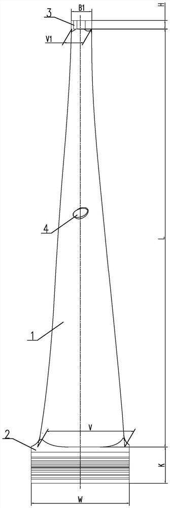
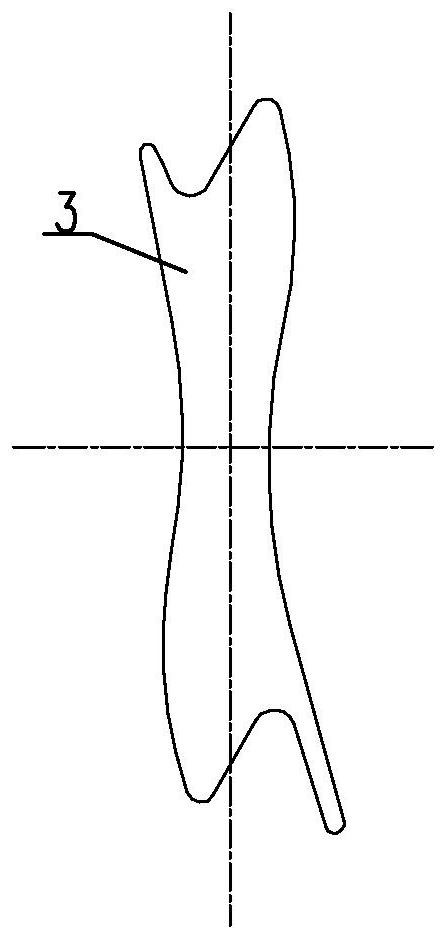
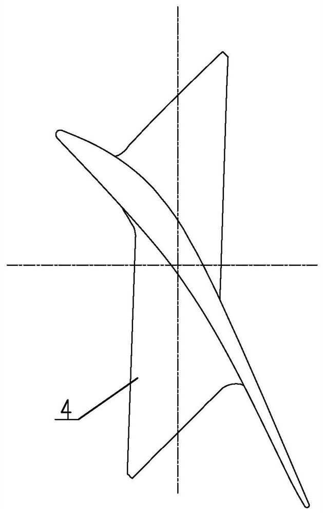
[0016] Specific implementation mode one: combine Figure 1 ~ Figure 4 Describe this embodiment, this embodiment is made up of blade working part 1, blade root 2, shroud 3 and boss tie bar 4, and shroud 3, blade work part 1, blade root 2 and boss tie bar 4 are from top to bottom The lower die is forged into one, and the profile of the working part 1 of the blade is a variable cross-section twisted blade, that is, there is a relative twist between two adjacent sections, and the cross-sectional area of ​​the working part 1 of the blade decreases gradually from the root to the top; the height of the working part 1 of the blade is L is 1000mm, the axial width V of the root of the blade working part 1 is 206.83mm, the root diameter of the blade working part 1 is 1500mm, and the exhaust area of ​​the blade working part 1 is 3.37m 2 , the thickness H of the shroud 3 is 22mm, and the axial distance B1 of the working surface of the shroud 3 is 49.47mm.

specific Embodiment approach 2

[0017] Specific implementation mode two: combination figure 1 , Figure 4 , Figure 5 and Figure 6 To illustrate this embodiment, the variation range from the root axial width V of the blade working part 1 to the top axial width V1 of the blade working part 1 in this embodiment is 206.83 mm to 47.68 mm, and the variation range of the chord length b is 208.99 mm to 208.99 mm. 171.74mm, installation angle β y The variation range of the maximum profile thickness T is 23.2mm to 6.37mm, the variation range of the inlet angle α is 56.72°~161.1°, and the variation range of the outlet angle θ is 38.32°~24.9° . By adopting the above structural parameters, the blades can be easily assembled while ensuring that the outer structure dimensions of the blades meet the design requirements. Other components and connections are the same as those in the first embodiment.

specific Embodiment approach 3

[0018] Specific implementation mode three: combination figure 1 , Figure 4 , Figure 5 and Figure 6 Describe this embodiment, the height L of blade working part 1 of this embodiment is respectively 0mm, 200mm, 400mm, 650mm, 900mm, 1000mm, and the corresponding axial width V of blade working part 1 is respectively: 206.83mm, 164.31mm , 129.74mm, 88.43mm, 53.79mm, 47.68mm, the corresponding chord length b is respectively: 208.99mm, 169.27mm, 152.28mm, 157.9mm, 168.28mm, 171.74mm, and the corresponding installation angle β y They are respectively: 82.3°, 76.49°, 58.56°, 33.91°, 18.33°, 15.84°, and the corresponding maximum thickness T of the molding line are: 23.2mm, 25.87mm, 22.24mm, 12.48mm, 8.16mm, 6.37 mm, the corresponding inlet angle α is respectively: 56.72°, 46.15°, 66.75°, 123.53°, 153.52°, 161.1°, and the corresponding outlet angle θ is respectively: 38.32°, 37.69°, 33.2°, 27.16 °, 24.49°, 24.9°. By adopting the above structural parameters, the blades can be easi...


PUM


Abstract

The invention relates to a 1000mm last-stage moving blade, in particular to a 1000mm last-stage moving blade for a 3000rpm full-rotation-speed steam turbine. The problem that an existing last-stage long blade cannot meet the requirements of units with different capacity grades is solved. A shroud ring (3), a blade working part (1), a blade root (2) and a boss lacing wire (4) are forged into a whole from top to bottom, the molded line of the blade working part (1) is a variable cross-section twisted blade, that is, two adjacent cross sections are twisted relatively, the area of the cross section of the blade working part (1) is gradually reduced from the root to the top, the height (L) of the blade working part (1) is 1000 mm, the axial width (V) of the root of the blade working part (1) is 206.83 mm, the diameter of the root of the blade working part (1) is 1500 mm, the steam exhaust area of the blade working part (1) is 3.37 m < 2 >, the thickness (H) of the shroud ring (3) is 22 mm, and the axial distance (B1) of the working face of the shroud ring (3) is 49.47 mm. The 1000mm last-stage moving blade is applied to 3000rpm full-rotation-speed steam turbine.

Description

technical field [0001] The invention relates to a 1000mm final stage moving blade, in particular to a 1000mm final stage moving blade for a 3000rpm full speed steam turbine. Background technique [0002] With the development of the electricity market, it is necessary to develop steam turbines with different capacities according to different demands. At the same time, due to the increasingly stringent requirements on carbon emissions, it is necessary to develop more efficient steam turbines. Since the power generated by the last-stage moving blades accounts for more than 10% of the total power of the steam turbine, the last-stage long blades play an important role in the development of high-power steam turbines and the improvement of unit economy. At the same time, due to the harsh working conditions of the last-stage long blades, it not only requires careful design in terms of aerodynamics, strength and vibration analysis, but also requires a high level of technology in mat...

Claims


Application Information

Patent Timeline
Patent Type & Authority Applications(China)
IPC IPC(8): F01D5/14F01D5/30F01D5/26
CPCF01D5/141F01D5/147F01D5/3007F01D5/26
Inventor 管继伟刘长春郭魁俊李宇峰刘云锋马义良赵洪羽关淳潘春雨马天吟梁天赋刘鑫王丽华胡炳南李央武芏茳刘瑶王健
Owner HARBIN TURBINE
Why Eureka
Try Eureka