IDC peeling-free wire connection mechanism

A stripping-free and wire-free technology, applied in the direction of connection, conductive connection, clamping/spring connection, etc., can solve the problem of large wire diameter and large operating force of stripping-free connection, avoid adverse effects, facilitate processing, and improve strength Effect

Active Publication Date: 2018-11-27
PHOENIX ASIAN PACIFIC ELECTRIC NANJING
View PDF16 Cites 0 Cited by
  • Summary
  • Abstract
  • Description
  • Claims
  • Application Information

AI Technical Summary

Problems solved by technology

[0007] The purpose of the present invention is to provide an IDC non-stripping wire connection mechanism to solve the problem of large-diameter non-stripping wire connection operation force mentioned in the above-mentioned background technology

Method used


Image

  • IDC peeling-free wire connection mechanism
  • IDC peeling-free wire connection mechanism
  • IDC peeling-free wire connection mechanism

Examples


Embodiment 1

[0039] Example 1: See Figure 1-Figure 3 , the first technical solution of the present invention is: an IDC non-stripping wire connection mechanism, including a mounting shell, a switch knife conductive strip, an external conductive strip and a driver;

[0040] The installation shell is a rectangular shell structure, which is composed of a first right shell 1 and a first left shell 4 installed in one;

[0041] The external conductive strips include lath-shaped flat conductive strips 8 and side-plate conductive strips 7, and the side-plate conductive strips 7 are vertically attached to the sides of the flat conductive strips 8;

[0042] Described switch blade conductive strip is the semi-frame structure of bottom surface opening, comprises lath-shaped top surface conductive strip 2 and is connected to the shrapnel conductive strip 6 of top surface conductive strip 2 both sides and knife edge 5; Described knife edge 5 is made of two The block conductive strips are combined into...

Embodiment 2

[0051] Example 2: see Figure 4-Figure 6, the difference between the second technical solution of the present invention and the first technical solution is that the switch knife conductive strip is different from the external conductive strip, that is: the switch knife conductive strip is a semi-frame structure with an opening on the bottom surface, including a strip-shaped The top surface conductive strip 2 and the straight conductive strip 10 and the knife edge 5 connected to the two sides of the top surface conductive strip 2; the knife edge 5 is composed of two conductive strips into a figure-eight structure, and is vertically fixed to the top surface conductive strip 2; the flat conductive strip 10 is vertically fixed to the lower end of the top conductive strip 2;

[0052] The external conductive strip includes a flat conductive strip 8 and a U-shaped shrapnel conductive strip 11 fixedly connected to the flat conductive strip 8, and the opening end of the U-shaped elasti...

Embodiment 3

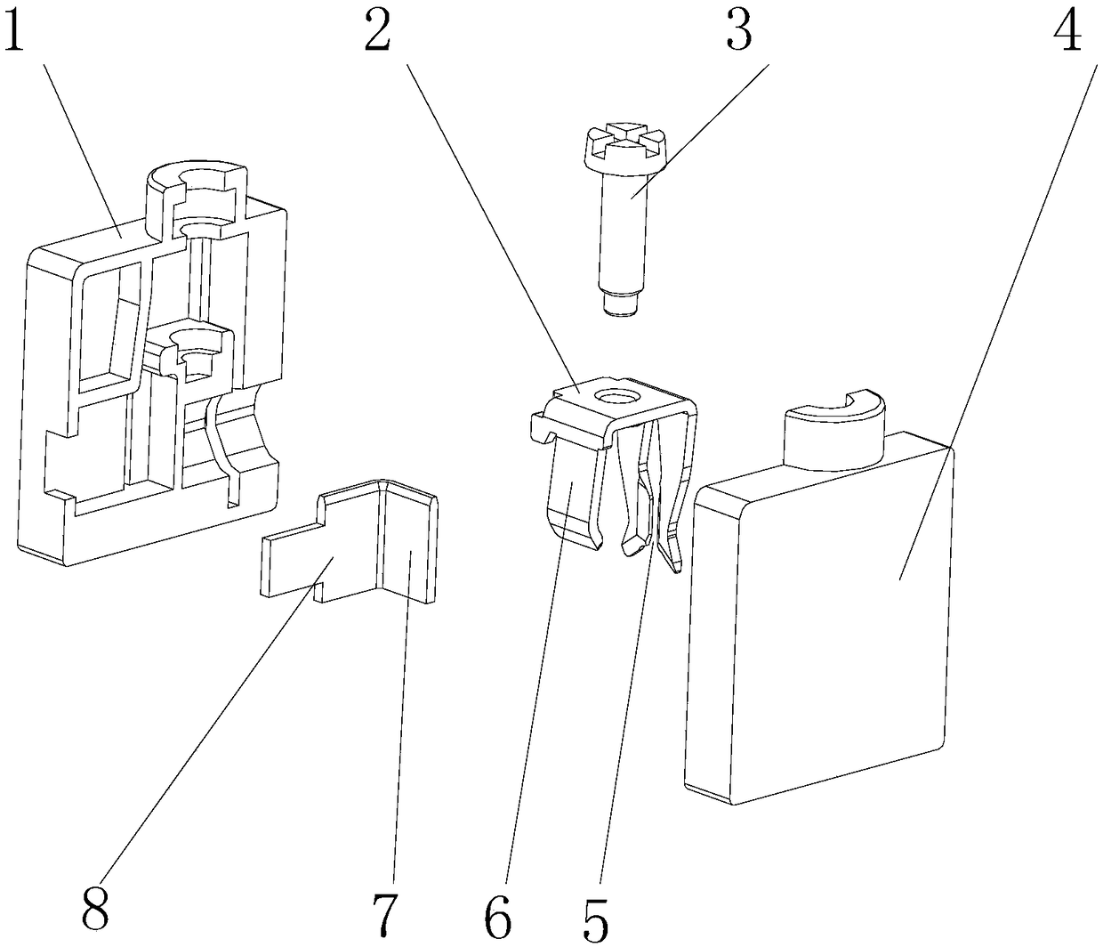
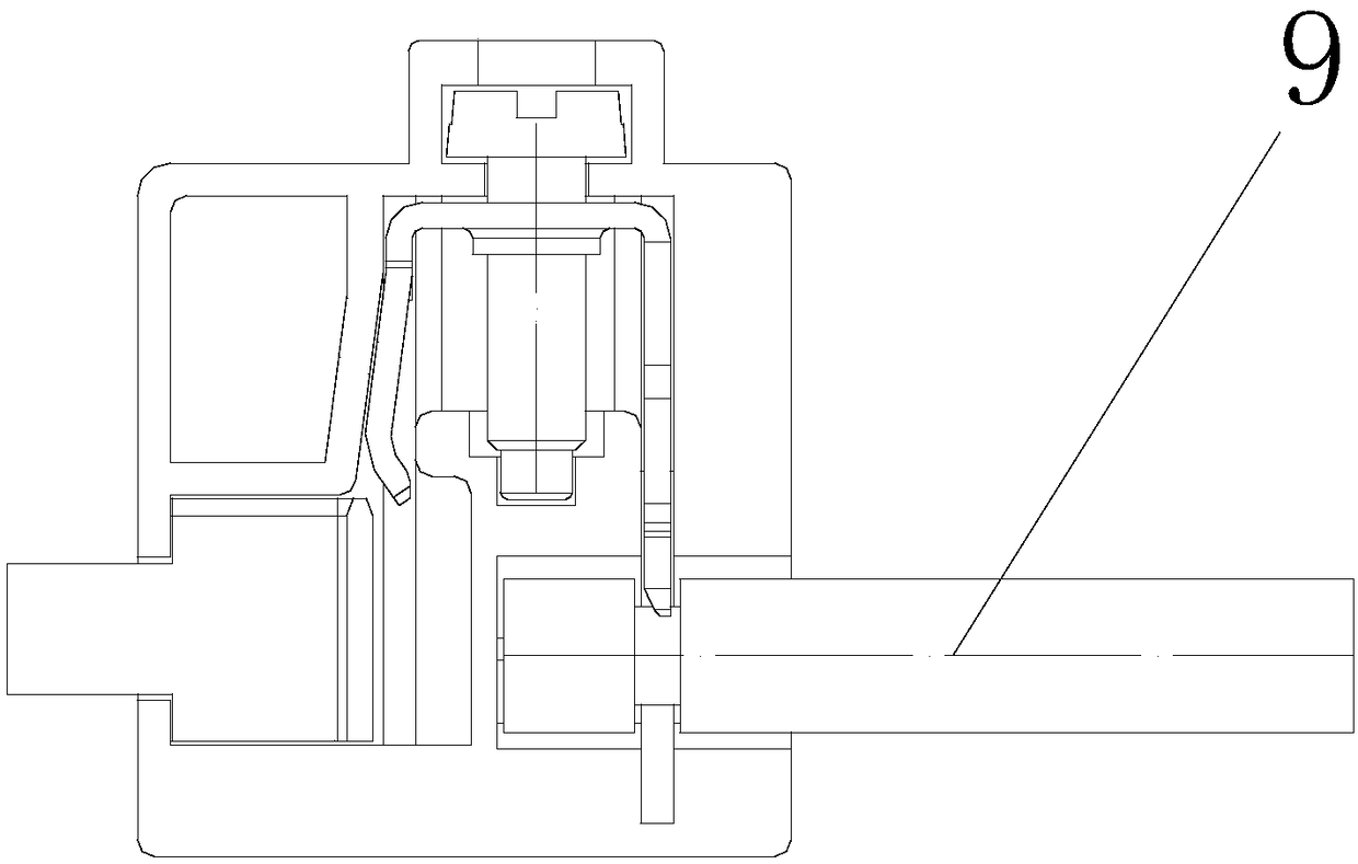
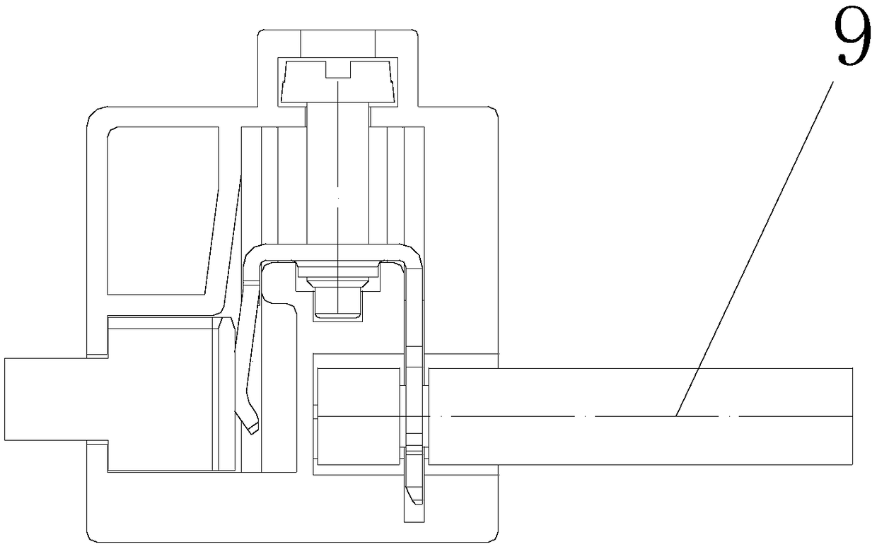
[0055] Example 3: See Figure 7-Figure 10 The difference between the third technical solution of the present invention and the first technical solution is that it also includes an inner casing and a nut 12; the inner casing is a rectangular casing structure, and the second right casing 13 installed in one Composed of the second left casing 14; the inner casing can be reciprocated up and down and installed on the upper part of the installation casing;

[0056] The switch knife conductive strip is fixedly installed at the inner lower end of the inner casing, and the shrapnel conductive strip 6 and the knife edge 5 are exposed on the lower side of the inner casing;

[0057] The screw 3 is rotatably installed on the inner upper end of the inner casing, the upper end of the screw 3 is fixedly connected to the top conductive strip 2, and the lower end is exposed on the lower side of the inner casing;

[0058] The nut 12 is fixedly installed in the middle of the installation housing...


PUM


Abstract

The invention discloses an IDC peeling-free wire connection mechanism, which comprises an installing casing used for fixing a conducting wire and also comprises a switch conducting strip and a driver,wherein the switch conducting stirp is used for cutting the conducting wire and is conducted and connected with the conducting wire; the driver is used for driving the switch conducting strip and theconducting wire to realize conduction or break the connection; the driver and the switch conducting strip are arranged in the installing casing; the driver drives the switch conducting strip to do reciprocating movement. In the practical wire connection operation; the pretreatment on the conducting wire is not needed, i.e., during wire connection, a screw rotates, and the switch conducting stripis driven to downwards move, so that an insulation layer of the conducting wire is cut by a cutting edge; a copper core is directly connected with the cutting edge; the conduction is realized; the adverse influence due to wire peeling nonconformance is avoided.

Description

technical field [0001] The invention relates to the technical field of connector wiring, in particular to an IDC wire-stripping-free wiring mechanism. Background technique [0002] The wiring techniques commonly used in existing electrical connector products are: screw wiring technology and spring wiring technology. When wiring, it is usually necessary to pre-treat the wires first, that is: according to the stripping length specification of the product, a certain length of insulation layer is stripped from the wire end, and then the exposed copper core is connected to the screw wiring device or spring wiring device to achieve conduction. [0003] However, in the actual wiring operation, due to the uneven professionalism of the wiring operators, when the deviation of the stripped wire length is large, the electrical performance of the electrical connector is easily affected. When the stripping length is too short, the conductive strip is easy to be pressed against the insul...

Claims


Application Information

Patent Timeline
Patent Type & Authority Applications(China)
IPC IPC(8): H01R4/2429H01R4/2475H01R4/48
CPCH01R4/2429H01R4/2475H01R4/4809
Inventor 车敏
Owner PHOENIX ASIAN PACIFIC ELECTRIC NANJING
Why Eureka
Try Eureka