Coated sand mold loading and positioning installation template

A technology for positioning, installing and installing templates, which is applied in the directions of manufacturing tools, casting and molding equipment, and parts of molding machines. The effect of manpower and easy installation

Pending Publication Date: 2018-11-30
YUZHOU KUNLUN MOLD CO LTD
View PDF12 Cites 0 Cited by
  • Summary
  • Abstract
  • Description
  • Claims
  • Application Information

AI Technical Summary

Problems solved by technology

[0003] Coated sand molds have not yet formed a unified installation standard and specification in China. Therefore, in order to match different coated sand molds, it is necessary to design different installation templates for installing fixed coated sand molds, which brings a huge workload to the manufacturer. , which increases the production cost of the enterprise
And each time a different coated sand mold is used for production, different installation templates need to be replaced, which consumes the physical strength of the on-site operators and the production efficiency is not high

Method used


Image

  • Coated sand mold loading and positioning installation template
  • Coated sand mold loading and positioning installation template
  • Coated sand mold loading and positioning installation template

Examples


Embodiment 1

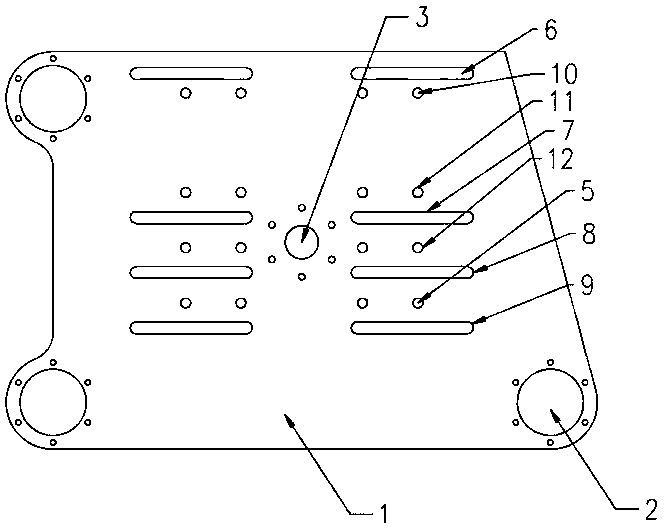
[0022] Embodiment 1: as figure 1 and 2 The shown coated sand mold clamping and positioning installation template includes a body 1 of the installation template, guide holes 2 are provided around the body 1, a fixing hole 3 is provided in the middle of the body 1, and the body 1 on both sides of the fixing hole 3 There are strip-shaped channel groups and circular channel groups arranged symmetrically on the upper part. The strip-shaped tunnel group includes a first strip-shaped tunnel 6, a second strip-shaped tunnel 7, a third strip-shaped tunnel 8, and a fourth strip-shaped tunnel 9 arranged sequentially from top to bottom on the body 1; the circular tunnel The group includes two first circular tunnels 10 arranged side by side below the first strip-shaped tunnel 6, two second circular tunnels 11 arranged side by side above the second strip-shaped tunnel 7, and arranged side by side at the third strip-shaped tunnel 8 The two upper third circular holes 12 and the two fourth ci...

Embodiment 2

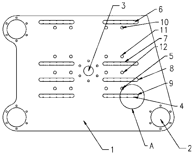
[0025] Embodiment 2: be optimal embodiment of the present invention, as figure 2 , 3 4. The coated sand mold clamping and positioning installation template shown in 4 includes a body 1 of the installation template. Guide holes 2 are arranged around the body 1, and a fixing hole 3 is arranged in the middle of the body 1. The fixing holes 3 on both sides of the fixing hole 3 The main body 1 is symmetrically provided with a strip-shaped channel group and a circular channel group. The strip-shaped tunnel group includes a first strip-shaped tunnel 6, a second strip-shaped tunnel 7, a third strip-shaped tunnel 8, and a fourth strip-shaped tunnel 9 arranged sequentially from top to bottom on the body 1; the circular tunnel The group includes two first circular tunnels 10 arranged side by side below the first strip-shaped tunnel 6, two second circular tunnels 11 arranged side by side above the second strip-shaped tunnel 7, and arranged side by side at the third strip-shaped tunnel 8...


PUM


Abstract

The invention relates to a coated sand mold loading and positioning installation template. The coated sand mold loading and positioning installation template comprises an installation template body. Guiding holes are formed in the periphery of the installation template body. A fixing hole is formed in the middle of the installation template body. Bar-shaped hole path sets and circular hole path sets are symmetrically arranged on the portion, on the two sides of the fixing hole, of the installation template body. The coated sand mold loading and positioning installation template is simple in structure and suitable for a plurality of coated sand molds. Installation templates matched with different coated sand molds do not need to be produced when the different coated sand molds are used. Theresearch and development and production cost of enterprises is saved. The coated sand mold loading and positioning installation template is easy to install and suitable for manual operation, can be applied to the plurality of coated sand molds after one-time installation of the coated sand mold loading and positioning installation template on equipment like a core shooter, saves manpower and working time, and effectively improves working efficiency.

Description

technical field [0001] The invention belongs to the technical field of mold machinery, and in particular relates to a clamping and positioning installation template for a coated sand mold. Background technique [0002] The core shooting machine uses coated sand to make cores, and is suitable for both hot core boxes and cold core boxes. The core shooting machine is characterized by the application of two guide pillars, the vertical parting of the opening and closing molds, and the installation of two different molds at the same time, the middle fixed frame can be installed on both sides of the fixed mold, and the left and right opening and closing molds are equivalent to double mold frames. The core shooter is widely used in the foundry industry. The cores made by the core shooter are accurate in size and smooth in surface. The working principle of the core shooting machine is to inject the core sand mixture with liquid or solid thermosetting resin as the binder into the hea...

Claims


Application Information

Patent Timeline
Patent Type & Authority Applications(China)
IPC IPC(8): B22C15/24B22C19/00
CPCB22C15/24B22C19/00
Inventor 李向阳
Owner YUZHOU KUNLUN MOLD CO LTD
Why Eureka
Try Eureka