Clamp locating device for lathe

A fixture positioning device, lathe technology, applied in positioning devices, clamping, manufacturing tools and other directions, can solve the problems of not being able to ensure production operation well, reducing the work efficiency of operators, failing to meet design requirements, etc., and achieving a simple structure. Reasonable, improved rigidity, good dimensional consistency

Inactive Publication Date: 2018-11-30
芜湖恒跃智能装备有限公司
View PDF6 Cites 1 Cited by
  • Summary
  • Abstract
  • Description
  • Claims
  • Application Information

AI Technical Summary

Problems solved by technology

[0004] The purpose of the present invention is to provide a fixture positioning device for lathes to solve the problem of deviation caused by insufficient rigidity due to too long and small diameter of the workpiece during the positioning process on the general chuck proposed in the above-mentioned background technology, and it is difficult to ensure the accuracy. Failure to meet the original design requirements has greatly increased the scrap rate, reduced the work efficiency of operators, and failed to ensure normal production operations.

Method used


Image

  • Clamp locating device for lathe
  • Clamp locating device for lathe
  • Clamp locating device for lathe

Examples


Embodiment Construction

[0017] The following will clearly and completely describe the technical solutions in the embodiments of the present invention with reference to the accompanying drawings in the embodiments of the present invention. Obviously, the described embodiments are only some, not all, embodiments of the present invention. Based on the embodiments of the present invention, all other embodiments obtained by persons of ordinary skill in the art without making creative efforts belong to the protection scope of the present invention.

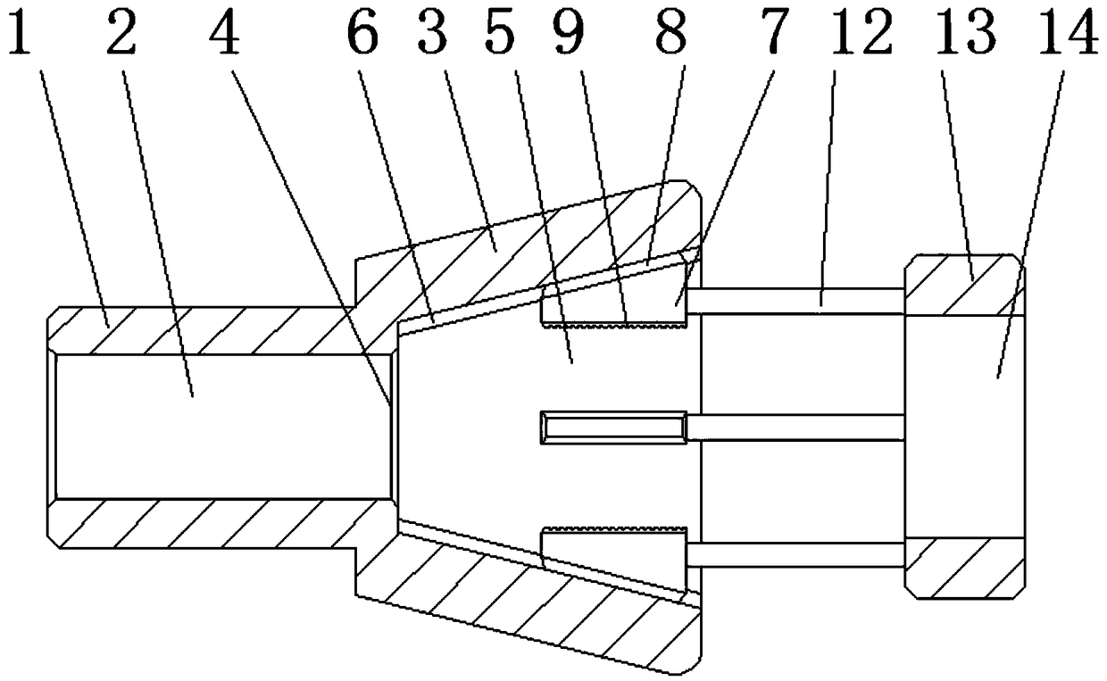
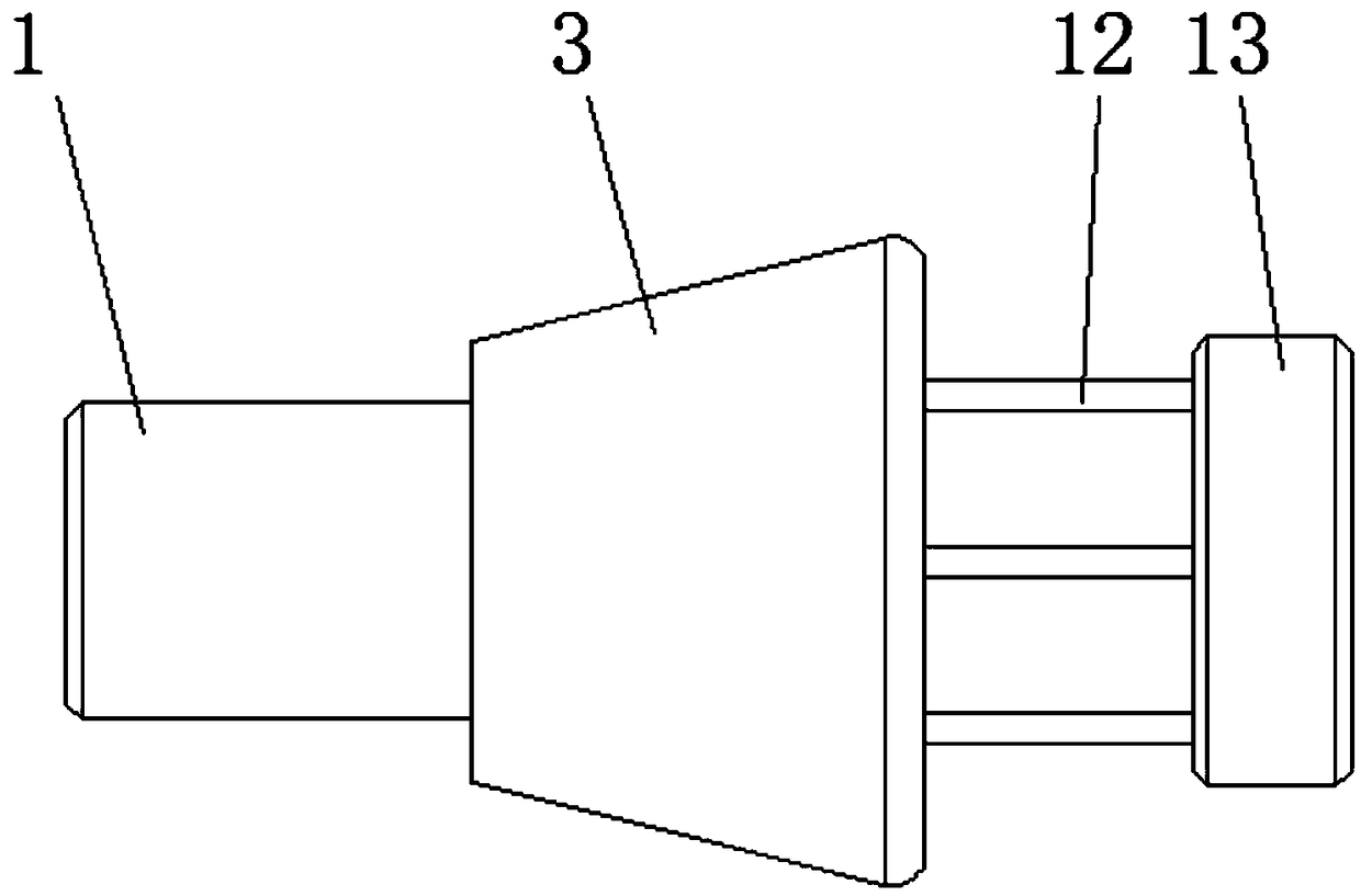
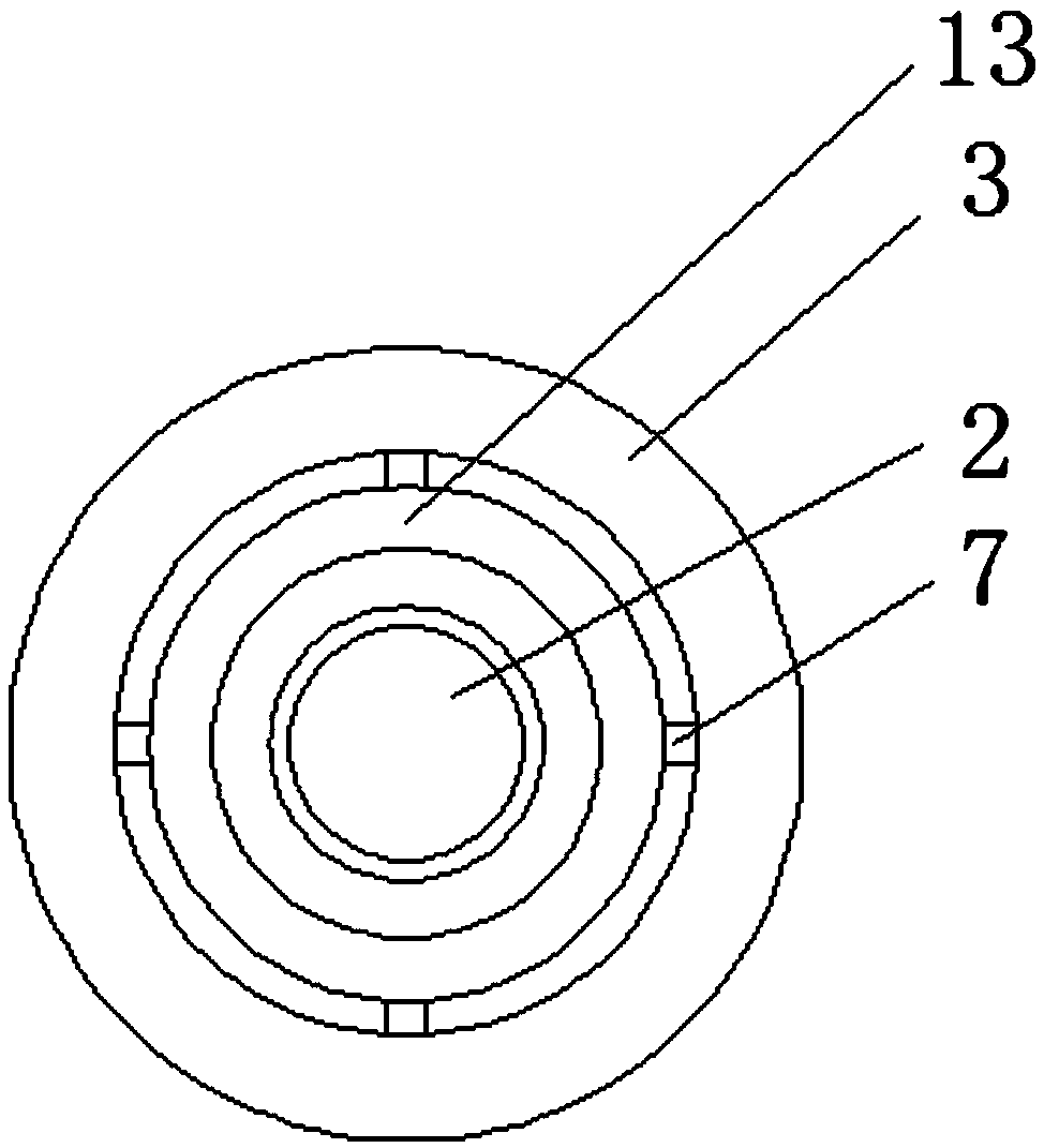
[0018] see Figure 1-4 , the present invention provides a technical solution: a fixture positioning device for a lathe, including a connecting head 1, a clamping opening 5, a clamping jaw 7 and a movable block 11, the inside of the connecting head 1 is provided with a workpiece socket 2, and the connecting head The right side of 1 is provided with a vertebral body 3. The vertebral body 3 can be matched with the inner hole at the right end of the lathe spindle,...


PUM


Abstract

The invention discloses a clamp locating device for a lathe. The clamp locating device comprises a connector, a clamping port, clamping jaws and a movable block, wherein the connector is internally provided with a workpiece socket, and the right side of the connector is provided with a cone. The left end of the cone is provided with a circular chamfer located at the right end of the workpiece socket, the upper end of the clamping port is provided with a circumferential tooth, helical teeth are arranged above the clamping jaws and below the circumferential tooth, and anti-slip teeth are disposed under the clamping jaws. Connecting rods are connected to the right side of the movable block, and an operating panel is mounted on the right sides of the connecting rods. Compared with the existingordinary lathe clamp, the clamp locating device has the advantages of simple and reasonable structure, easy manufacture, low cost and wide application range. By means of the clamp locating device, production of batch parts can be uniform in process standard and good in size consistency. At the same time, the range of machined parts is greatly increased, and the practicality is improved.

Description

technical field [0001] The invention relates to the technical field of lathe fixture positioning, in particular to a lathe fixture positioning device. Background technique [0002] Lathe fixture refers to the fixture used to process the inner and outer rotary surfaces and end faces of the workpiece on the lathe. The positioning of the workpiece is a very important link during processing. [0003] At present, when using a three-grip chuck to clamp and produce a large number of parts on a machine tool, when using a three-grip chuck for positioning, only the positioning disc or hole parts can be processed, and the positioning ability of the fixture will decrease when processing some shaft parts. If the diameter of the machining shaft is smaller than the diameter of the inner hole of the three-grip chuck or the inner diameter of the spindle, positioning on the chuck will not work, and the protruding length is too long, and the workpiece will be offset due to insufficient rigidit...

Claims


Application Information

Patent Timeline
IPC IPC(8): B23Q3/12
CPCB23Q3/12
Inventor 刘永泽
Owner 芜湖恒跃智能装备有限公司
Why Eureka
Try Eureka