Polishing device of clutch brake disc of washing machine

A polishing device and clutch technology, which are applied in the directions of grinding machine parts, grinding/polishing equipment, and workpiece feed motion control, can solve problems such as low work efficiency and poor polishing effect, and achieve guaranteed and fixed effects. Plus, the effect of less number of position adjustments

Active Publication Date: 2018-11-30
宁国市金泰金属制品有限公司
View PDF6 Cites 2 Cited by
  • Summary
  • Abstract
  • Description
  • Claims
  • Application Information

AI Technical Summary

Problems solved by technology

[0003] The purpose of the present invention is to solve the problem of low work efficiency and poor polishing effect, and propose a polishing device for clutch brake disc of washing machine

Method used


Image

  • Polishing device of clutch brake disc of washing machine
  • Polishing device of clutch brake disc of washing machine
  • Polishing device of clutch brake disc of washing machine

Examples


Embodiment 1

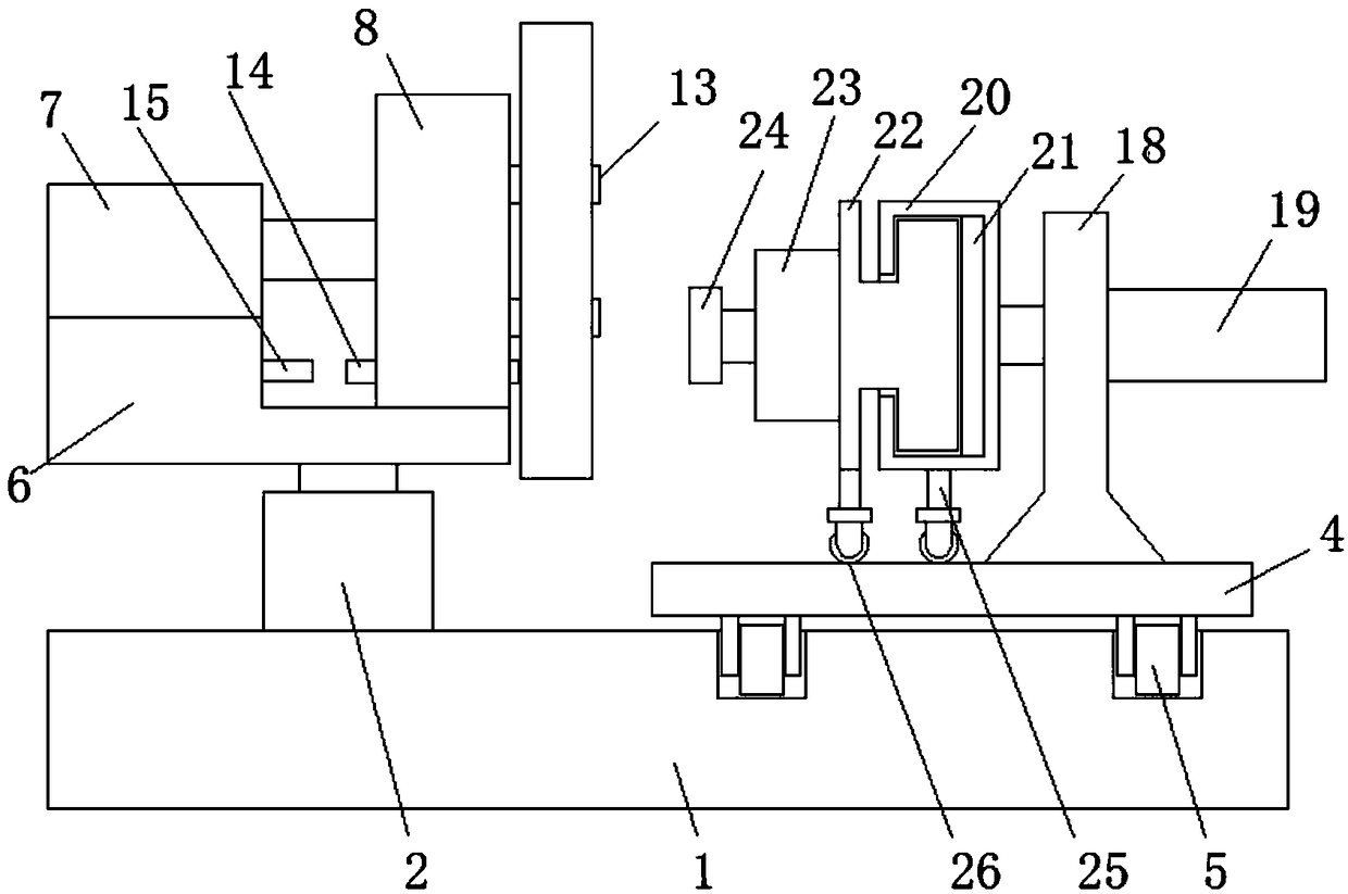
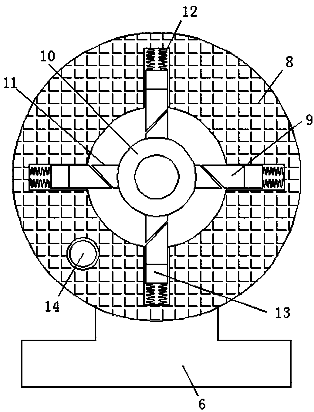
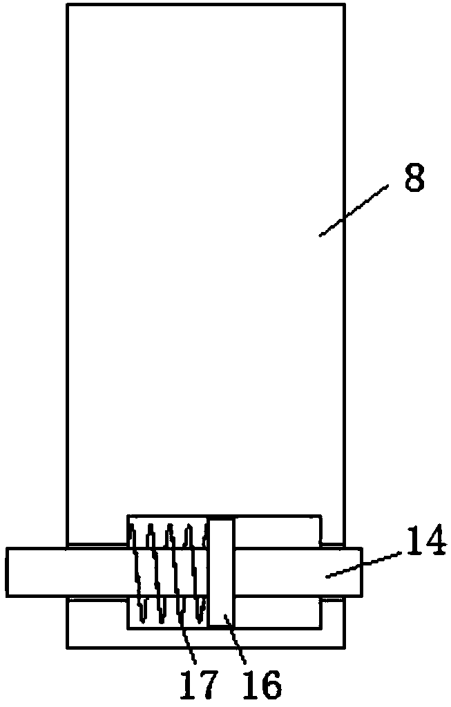
[0026] refer to Figure 1-4 , a washing machine clutch brake disc polishing device, including a working base 1, the top of the working base 1 is fixed with a Z-axis cylinder 2 and a Y-axis cylinder 3 by bolts, and the top of one side of the working base 1 is an L-shaped structure , and the Y-axis cylinder 3 is installed on the vertical inner side of the working base 1, and a sliding seat 4 is arranged vertically above the working base 1. The output rod of the Y-axis cylinder 3 is fixedly connected to one side of the sliding seat 4, and the sliding The bottom side of the seat 4 is provided with a track wheel 5, and the top side of the working base 1 is provided with a track groove, the track wheel 5 is slidably connected in the track groove, and the output rod of the Z-axis cylinder 2 is fixedly connected with an L-shaped mounting plate 6. The top side of the shape mounting plate 6 is equipped with a rotating motor-7, and the output shaft of the rotating motor-7 is fixedly conn...

Embodiment 2

[0028] Such as figure 1 with figure 2 As shown, this embodiment is basically the same as Embodiment 1. Preferably, the grinding mechanism includes a Y-shaped mounting plate 18, which is fixedly installed on the top side of the sliding seat 4, and one part of the Y-shaped mounting plate 18 The X-axis cylinder 19 is fixedly installed on the side by bolts, and the output rod of the X-axis cylinder 19 is fixedly connected with the connecting cylinder 20. The side of the connecting cylinder 20 close to the clamp rod 13 is provided with a T-shaped groove, and the vertical of the T-shaped groove is A pressure sensor 21 is fixedly installed on the inner wall of one side, and an I-shaped mounting plate 22 is arranged in the T-shaped groove, and one end of the I-shaped mounting plate 22 extends to the side of the connecting cylinder 20 close to the clamp rod 13 and is fixedly installed with a second rotating motor. 23, the output shaft transmission of rotating motor two 23 is provided...

Embodiment 3

[0030] Such as figure 1 with figure 2 As shown, this embodiment is basically the same as Embodiment 1 or Embodiment 2. Preferably, auxiliary support rods 25 are fixedly welded to the bottom sides of the connecting cylinder 20 and the I-shaped mounting plate 22, and the bottom of the auxiliary support rods 25 Universal wheels 26 are provided at both ends, and the connecting cylinder 20 and the I-shaped mounting plate 22 are auxiliary supported respectively.


PUM


Abstract

The invention discloses a polishing device of a clutch brake disc of a washing machine, comprising a working base platform, of which the top is fixedly provided with a Z-axis cylinder and a Y-axis cylinder through a bolt; the top of one side of the working base platform is of an L-shaped structure; the Y-axis cylinder is installed in the vertical inner side of the working base platform; a slidingbase is vertically arranged above the working base platform; an output rod of the Y-axis cylinder is fixedly connected with one side of the sliding base; a track wheel is arranged at the bottom side of the sliding base; a track slot is arranged at the top side of the working base platform; the track wheel is slidingly connected in the track slot; an output rod of the Z-axis cylinder is fixedly connected with an L-shaped installation plate; a rotary motor I is installed at the top side of the L-shaped installation plate; and an output shaft of the rotary motor I is fixedly connected with a connecting round bar. The polishing device provided by the invention improves the production efficiency greatly, ensures the polishing effect of the clutch brake disc of the washing machine and meets theusing demands of people in production and life.

Description

technical field [0001] The invention relates to the technical field of home appliance production, in particular to a polishing device for a clutch brake disc of a washing machine. Background technique [0002] During the production process of the existing washing machine clutch brake disc, because the specific gravity around the center hole of the brake disc is not uniform, when the washing machine clutch brake disc is polished, it cannot be driven by the rotating motor to perform high-speed rotation and then polished. Therefore, people often use bolts or splints to fix the clutch brake disc of the washing machine on the operating table, and then perform manual polishing, which is inefficient and poor in polishing effect, and cannot meet people's needs in production and life. Contents of the invention [0003] The purpose of the present invention is to solve the problems of low working efficiency and poor polishing effect, and propose a polishing device for a clutch brake ...

Claims


Application Information

Patent Timeline
Patent Type & Authority Applications(China)
IPC IPC(8): B24B19/00B24B49/02
Inventor 张东放张潇周军军张杰
Owner 宁国市金泰金属制品有限公司
Why Eureka
Try Eureka