Centrifugal printing cloth unwinding mechanism

An unwinding mechanism and inkjet cloth technology, which is applied in the direction of winding strips, thin material processing, transportation and packaging, etc., can solve the problem of easy slack in inkjet cloth rolls, and achieve improved unwinding quality, good effect, and stable unwinding Effect

Inactive Publication Date: 2018-11-30
太仓市霍普思机械技术有限公司
View PDF0 Cites 7 Cited by
  • Summary
  • Abstract
  • Description
  • Claims
  • Application Information

AI Technical Summary

Problems solved by technology

[0003] The purpose of the present invention is to solve the disadvantage that the inkjet cloth roll is easy to loosen when it stops in the prior art, and proposes a centrifugal type inkjet cloth unwinding mechanism

Method used


Image

  • Centrifugal printing cloth unwinding mechanism
  • Centrifugal printing cloth unwinding mechanism
  • Centrifugal printing cloth unwinding mechanism

Examples


Embodiment Construction

[0015] The following will clearly and completely describe the technical solutions in the embodiments of the present invention with reference to the accompanying drawings in the embodiments of the present invention. Obviously, the described embodiments are only some, not all, embodiments of the present invention.

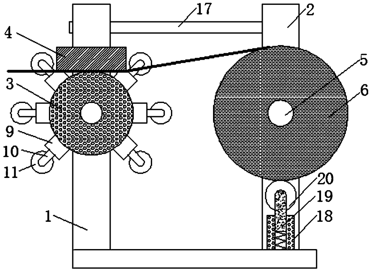
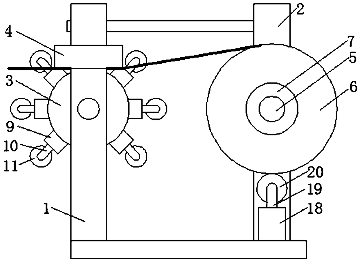
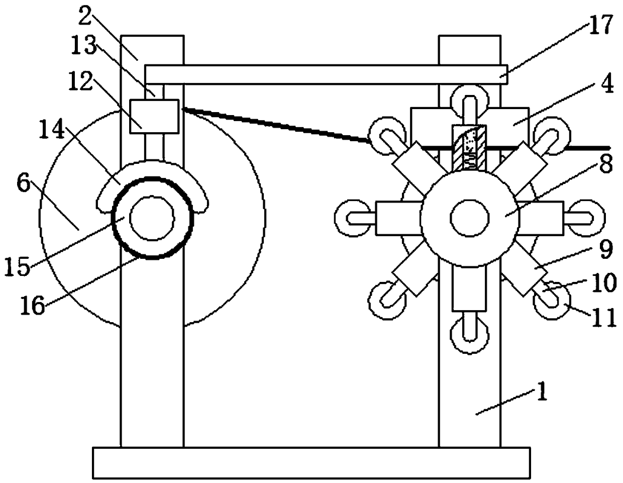
[0016] refer to Figure 1-3 , a centrifugal inkjet cloth unwinding mechanism, including a base plate, two upward left support plates 1 are provided on the left side of the upper end of the base plate, and an upward right support plate 2 is provided on the right rear side of the upper end of the base plate, two front and rear A left rotating shaft is rotatably connected between the left support plates 1, and a roller 3 is sleeved on the left rotating shaft. The through hole corresponding to the left support plate 1, the pressure plate 4 is against the roller 3, the lower end of the pressure plate 4 is provided with a resistance-increasing anti-skid rubber layer, which...


PUM


Abstract

The invention relates to the technical field of printing cloth roll unwinding, in particular to a centrifugal printing cloth unwinding mechanism. A top rod is inserted in a supporting cylinder, the lower end of the top rod is connected with the bottom end of an inner chamber of the supporting cylinder through an abutting spring, the upper end of the top rod is provided with a metering roller, andthe metering roller abuts against a printing cloth roll on the upper side. When stopping is performed, a traction disappears, resistance is provided under the action of a pressing plate, a roller stops, a telescopic rod is taken back under the action of a returning spring, and a top plate moves downwards; under the action of the gravity of the top plate and a brake rod, a friction plate presses abrake wheel to perform braking, so that the rotation of the printing cloth roll caused by inertia is prevented, a tightened state of a printing cloth is ensured, the unwinding quality is improved, sothat the pressing plate provides resistance to ensure unwinding stability; when stopping is performed, the pressing plate performs braking, at the same time a braking force is provided for a right rotating shaft, so that the printing cloth between the roller and the printing cloth roll keeps a tightened state and does not loosen, and an effect is better by the combination of the two.

Description

technical field [0001] The invention relates to the technical field of inkjet cloth roll unwinding, in particular to a centrifugal inkjet cloth unwinding mechanism. Background technique [0002] The structure of the existing inkjet cloth unwinding mechanism can only brake the pulled out inkjet cloth, but cannot brake the wound inkjet cloth roll, causing the inkjet cloth roll to continue to rotate and appear slack, affecting the unwinding quality and making it difficult to Meet the needs of production use. Contents of the invention [0003] The object of the present invention is to solve the disadvantage of easy slack when the inkjet cloth roll stops in the prior art, and propose a centrifugal type inkjet cloth unwinding mechanism. [0004] In order to achieve the above object, the present invention adopts the following technical solutions: [0005] Design a centrifugal inkjet cloth unwinding mechanism, including a base plate, two upward left support plates are provided o...

Claims


Application Information

Patent Timeline
Patent Type & Authority Applications(China)
IPC IPC(8): B65H23/06
CPCB65H23/06B65H2701/174
Inventor 张玉芹
Owner 太仓市霍普思机械技术有限公司
Why Eureka
Try Eureka