Eureka AIR delivers breakthrough ideas for toughest innovation challenges, trusted by R&D personnel around the world.

Depth imaging system and temperature error correction method thereof

A temperature error and imaging system technology, which is applied in the fields of optics and electronics, can solve the problems of the accuracy reduction of the depth imaging system, and achieve the effect of error correction and improvement of measurement accuracy

Pending Publication Date: 2018-11-30
SHENZHEN ORBBEC CO LTD
View PDF6 Cites 10 Cited by
  • Summary
  • Abstract
  • Description
  • Claims
  • Application Information

AI Technical Summary

Problems solved by technology

[0003] The present invention provides a depth imaging system and its temperature error correction method in order to solve the problem in the prior art that the temperature reduces the accuracy of the depth imaging system

Method used

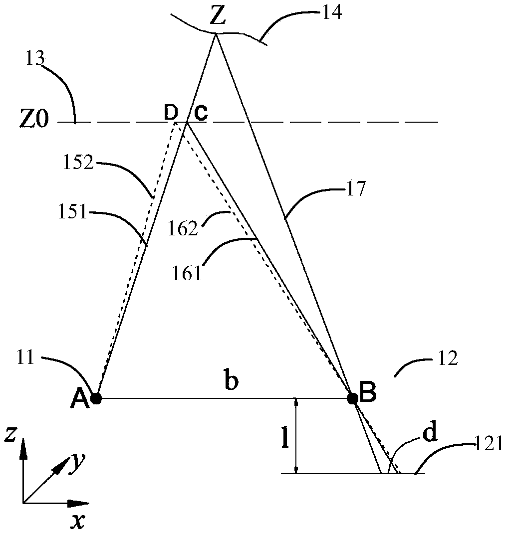
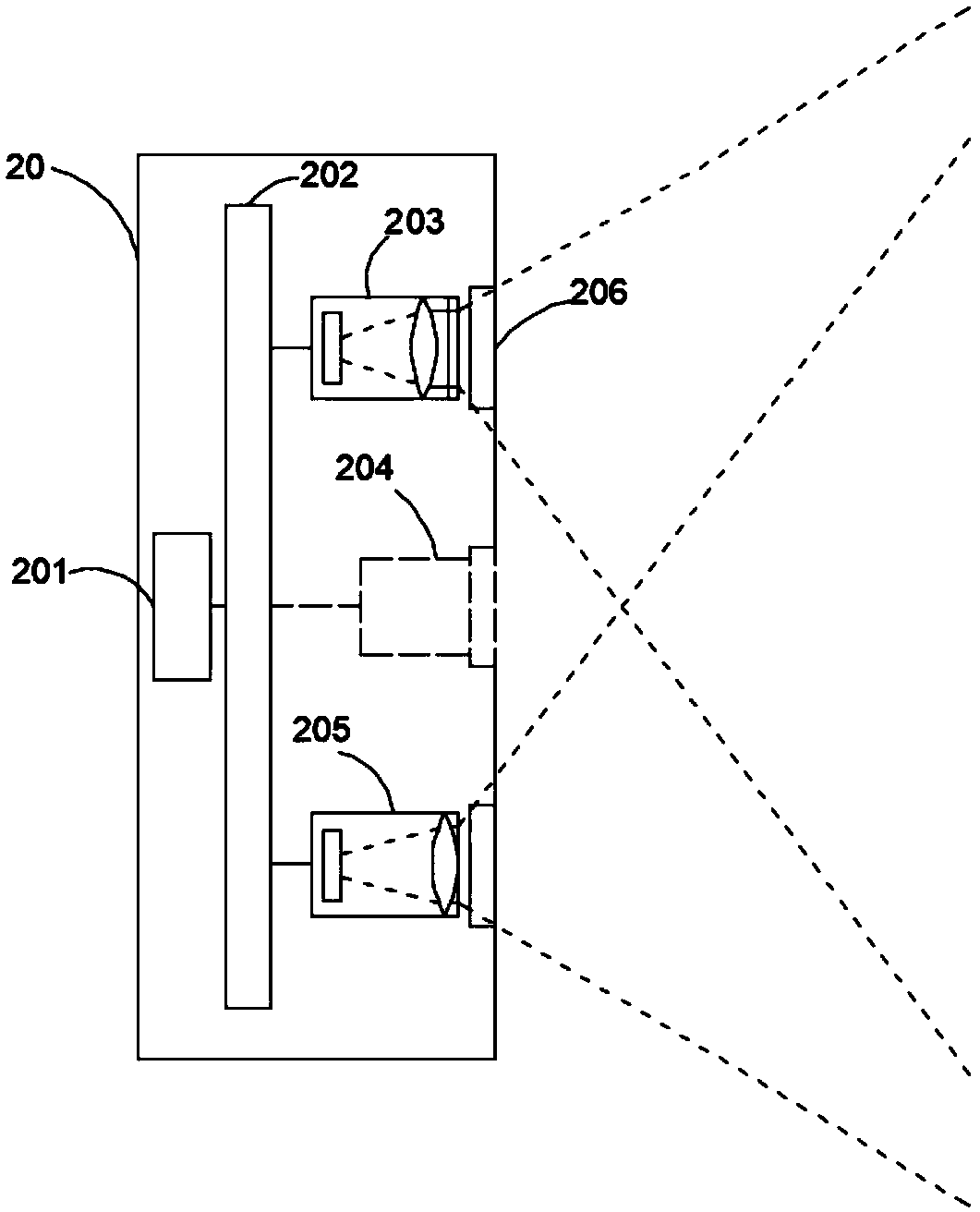
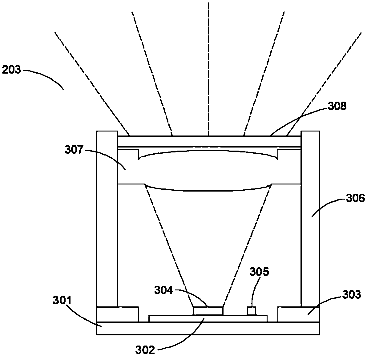

Image

  • Depth imaging system and temperature error correction method thereof
  • Depth imaging system and temperature error correction method thereof
  • Depth imaging system and temperature error correction method thereof

Examples


Embodiment Construction

[0020] The present invention will be described in further detail below in conjunction with specific embodiments and with reference to the accompanying drawings. It should be emphasized that the following descriptions are only exemplary and not intended to limit the scope of the present invention and its application.

[0021] In order to make the technical problems, technical solutions and beneficial effects to be solved by the embodiments of the present invention clearer, the present invention will be further described in detail below in conjunction with the accompanying drawings and embodiments. It should be understood that the specific embodiments described here are only used to explain the present invention, not to limit the present invention.

[0022] In addition, the terms "first" and "second" are used for descriptive purposes only, and cannot be interpreted as indicating or implying relative importance or implicitly specifying the quantity of indicated technical features....


PUM


Abstract

The invention provides a depth imaging system and a temperature error correction method. The temperature error correction method comprises the steps that a first reference structure light image and atarget structure light image are obtained; temperature error correction is conducted on the first reference structure light image, and a second reference structure light image is obtained; and the second reference structure light image and the target structure light image are utilized to conduct depth calculating, so that a depth image is obtained. Through the depth imaging system and the temperature error correction method, error correction of reference structure light can be achieved, thus error correction of depth measurement is achieved, and the measurement accuracy of the depth imaging system is improved finally.

Description

technical field [0001] The invention relates to the technical fields of optics and electronics, in particular to a depth imaging system and a temperature error correction method thereof. Background technique [0002] The structured light depth imaging system has been widely used in 3D modeling, somatosensory interaction, face recognition, AR and other fields due to its full-field measurement, high resolution, and real-time performance. One of the core components of the structured light depth imaging system is the structured light projection module, which is composed of lasers, optical elements and other devices, and is used to project a preset structured light image, which will inevitably be affected by temperature during the projection process , leading to a deviation between the projected structured light image and the preset structured light image, this deviation will directly affect the calculation of the subsequent depth image, and eventually lead to an error in the dep...

Claims


Application Information

Patent Timeline
Patent Type & Authority Applications(China)
IPC IPC(8): G01B11/22G01S17/89
CPCG01B11/22G01S17/89
Inventor 许星黄源浩
Owner SHENZHEN ORBBEC CO LTD
Why Eureka
Eureka Blog
Learn More