
True triaxial seepage test device under action of surrounding rock or soil

A test device, true triaxial technology, applied in measuring devices, using stable tension/pressure to test material strength, instruments, etc., can solve the problems of not considering the influence of underground structures and failing to reflect the stress of underground structures, etc. achieve the effect of ensuring safety and stability

Active Publication Date: 2018-11-30
ANHUI UNIV OF SCI & TECH
View PDF6 Cites 19 Cited by
  • Summary
  • Abstract
  • Description
  • Claims
  • Application Information

AI Technical Summary

Problems solved by technology

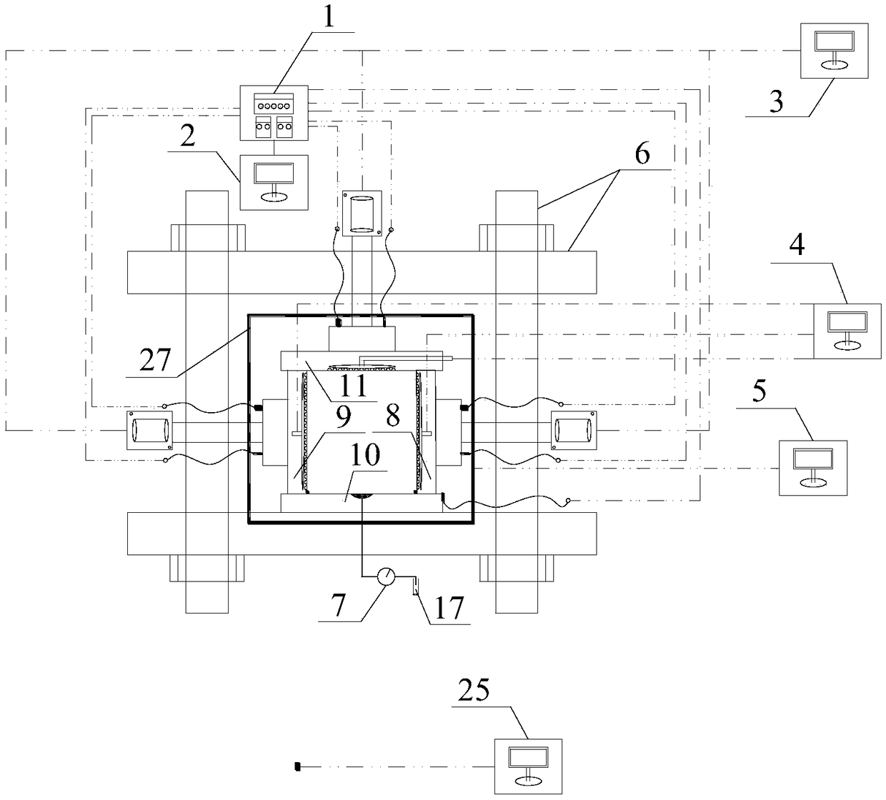
[0005] The purpose of the present invention is to provide a true triaxial seepage test device and test method under the action of surrounding rock or soil, to solve the problem that the current indoor test does not consider the effect of surr

Method used


Image

  • True triaxial seepage test device under action of surrounding rock or soil
  • True triaxial seepage test device under action of surrounding rock or soil
  • True triaxial seepage test device under action of surrounding rock or soil

Examples


Example Embodiment

[0086] Example 1

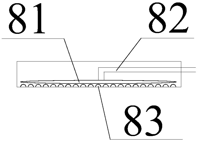
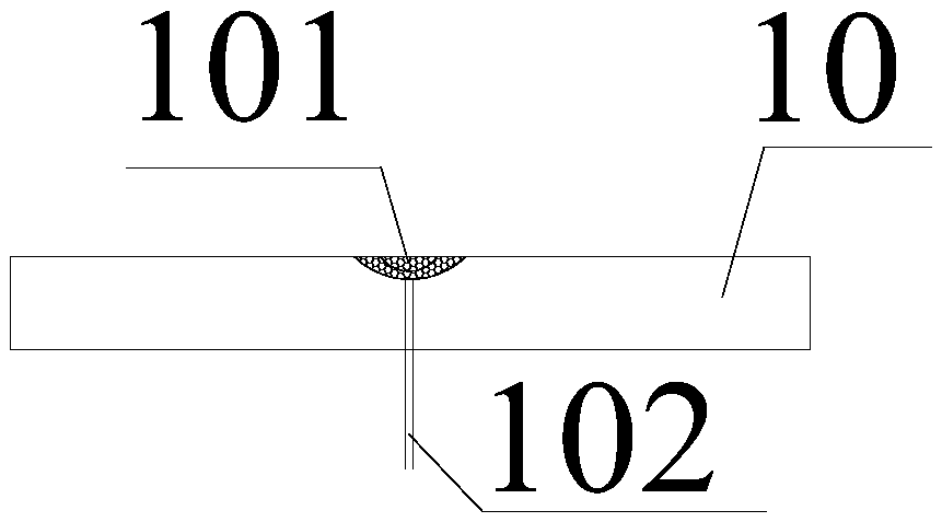
[0087] Since the prototype of the coal mine shaft is very large, only similar model theory can be used for model tests. During the working process of the shaft, there is groundwater seepage only in the circumferential direction, and there is no groundwater seepage at the upper and lower ends. Therefore, the servo seepage loading system 4 only controls the left side during the test. The water flow rate and water pressure of the seepage inlet conduit 82 of the right, front and rear pressure-bearing end plates, and the seepage control assembly of the upper pressure-bearing end plate 10 are temporarily disabled. Specific steps are as follows:

[0088] (1) Model making

[0089] Use similar theories to pour the model shaft wall and prepare appropriate similar materials to simulate the physical and mechanical properties of the surrounding rock or soil 20, and then use surrounding rock or soil 20 to tightly wrap the shaft wall in the center. The thickness of the surroundi...

Example Embodiment

[0099] Example 2

[0100] The underground structure is usually a concrete structure, so the prismatic concrete specimen 19 is used for the test. Depending on the situation, the prismatic concrete specimen 19 and the surrounding rock or soil 20 can be tested for lateral seepage mechanics, or the prismatic concrete specimen 19 and Axial seepage mechanics test of surrounding rock or soil 20, and a combination of the two, wherein the lateral seepage mechanics test method of prismatic concrete specimen 19 and surrounding rock or soil 20 is similar to the above-mentioned scheme 1, except that the object to be tested is different.

[0101] The test procedures of the axial seepage mechanics of the prism concrete specimen 19 and the surrounding rock or soil 20 are as follows:

[0102] (1) Model making

[0103] Pour the prismatic concrete specimen 19, then use the surrounding rock or soil 20 at the project site, or replace the surrounding rock or soil 20 with similar materials, and wrap the pri...

Example Embodiment

[0113] Example 3

[0114] The prismatic concrete specimen 19 and the surrounding rock or soil 20 both axially and laterally seepage mechanics test steps are basically the same as those in Example 2, except that in step (3), the servo seepage loading system 4 controls the left and The seepage water inlet conduit 82 of the right, front, and rear pressure-bearing end plates and the seepage water inlet conduit 112 of the upper pressure-bearing end plate apply water flow and corresponding water pressure to form a stable seepage around the test piece.


PUM


Abstract

The invention provides a true triaxial seepage test device under the action of surrounding rock or soil. The test device comprises: a frame, pressure-bearing end plates, a servo temperature control system, a stress deformation data acquisition and processing system, a servo control loading system, a servo hydraulic system, a servo seepage loading system and a wireless acoustic emission data acquisition and processing system. A test method of the test device comprises: model preparation, preparation before loading of a test piece to be detected, true triaxial seepage test under the action of surrounding rock (soil), and true triaxial seepage test stopping. The device simulates the true stress on the underground structure by a surrounding rock (soil) structure on the outer side of the underground structure, applies different stresses to the six pressure-bearing end plates, controls the flows and pressure of pressurized seepage water in different directions, acquires the real stress dataof the underground structure under combined action of surrounding rock (soil) through combination of multiple control systems and provides the scientific basis for the design and construction of the underground structure.

Description

technical field [0001] The invention belongs to the field of rock mechanics and engineering technology, and in particular relates to a true triaxial seepage test device and test method under the action of surrounding rock or soil. Background technique [0002] my country's underground space development has entered a stage of rapid development. Underground structures and surrounding rocks or soil are in contact with each other to bear external forces. Under the action of surrounding rocks or soil, the stress state of underground structures is also more complicated, especially for underground structures. It is also affected by the seepage of confined groundwater, so it is very important to analyze and evaluate the underground structure scientifically and rationally, and then obtain the true stress state and strength change law of the underground structure under the action of surrounding rock or soil, which provides a basis for the design and construction of underground structure...

Claims


Application Information

Patent Timeline
IPC IPC(8): G01N3/02G01N3/12G01N3/06
CPCG01N3/02G01N3/06G01N3/12G01N2203/0019G01N2203/0048G01N2203/0658
Inventor 薛维培程桦姚直书荣传新经纬蔡海兵王晓健宋海清郑腾龙黎明镜唐彬
Owner ANHUI UNIV OF SCI & TECH
Learn More