Compressed air energy storage system

A technology of compressed air energy storage and compressed air, which is applied in the direction of liquid variable capacity machinery, pumps, machines/engines, etc., and can solve the problem of affecting the safe operation of compressed air energy storage systems, poor working ability of compressed air, and air storage chambers. Life impact and other issues, to achieve the effect of improving thermal economy, increasing temperature, and improving efficiency

Inactive Publication Date: 2014-04-16
TSINGHUA UNIV +1
View PDF5 Cites 11 Cited by
  • Summary
  • Abstract
  • Description
  • Claims
  • Application Information

AI Technical Summary

Problems solved by technology

Therefore, the air storage chamber is always in periodic changes of cold and heat, which will not only affect the life of the air storage chamber, but also affect the safe operation of the compressed air energy storage system (for example: due to long-term cold and heat changes, the storage Fatigue and aging of chamber wall material), it will also affect the power consumption of the compressed air energy storage system (for example: during the process of compressed air energy storage, the temperature of the air storage chamber increases, resulting in an increase in compression power consumption; The reduction of the air temperature in the air chamber leads to the deterioration of the initial working ability of the compressed air, and additional fuel or heat is required to offset this part of the lost working ability)
[0004] In addition, the compressed air energy storage system will generate a large amount of low-grade heat energy (generally below 50°C) during operation without being utilized. Most compressed air energy storage systems discharge it directly into the natural environment, resulting in a large amount of low-grade waste of grade heat

Method used


Image

  • Compressed air energy storage system

Examples


Embodiment Construction

[0043] In order to make the object, technical solution and advantages of the present invention clearer, the present invention will be described in detail below through specific embodiments and with reference to the accompanying drawings.

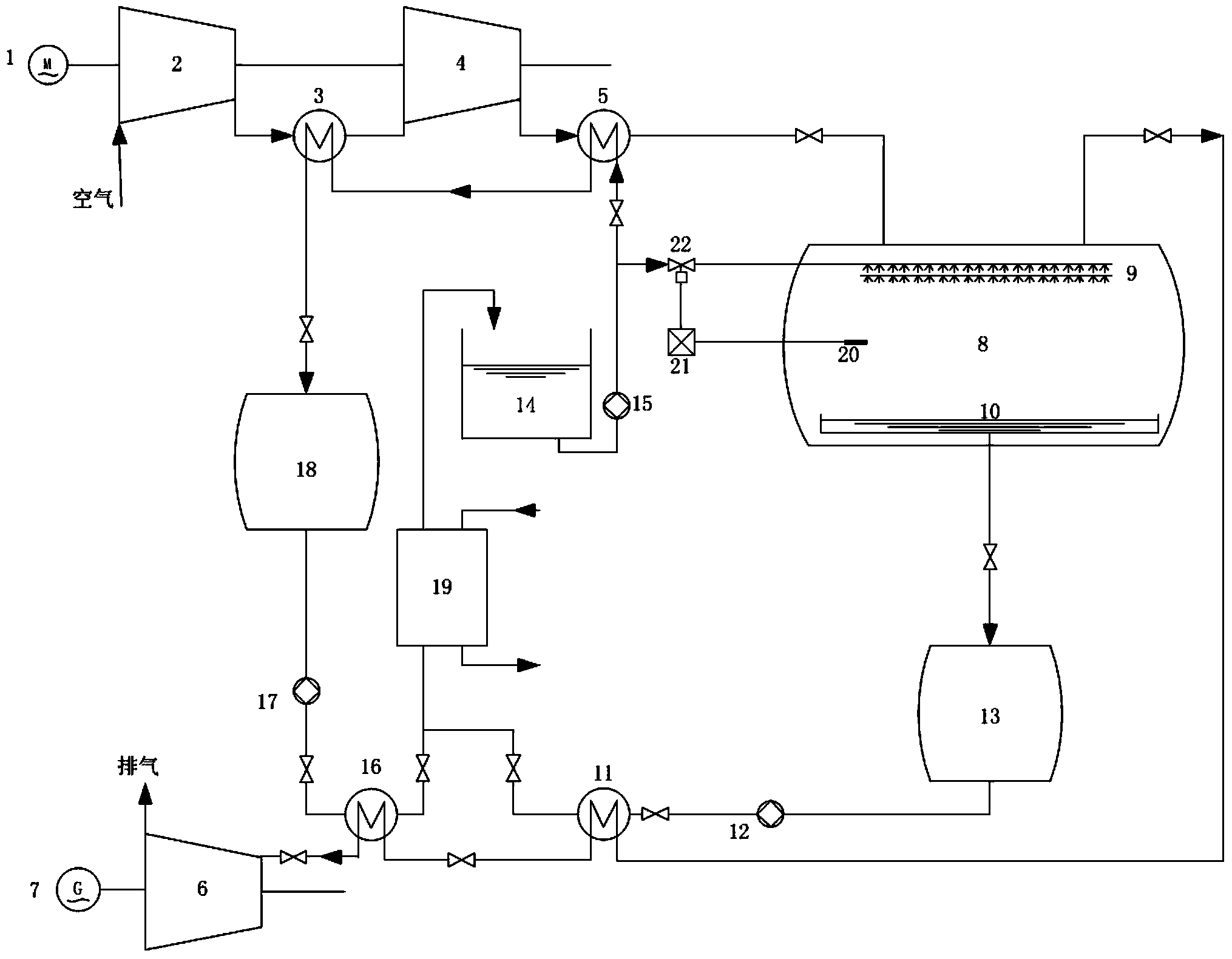
[0044] An embodiment of the present invention provides a compressed air energy storage system, such asfigure 1 As shown, it includes: a motor 1, an air compressor unit connected to the motor 1, an air storage chamber 8 for storing compressed air, and a temperature controller for controlling the temperature in the air storage chamber 8;

[0045] The air storage chamber 8 is provided with an atomizing water spray mechanism 9 for keeping the temperature of the stored compressed air relatively stable and a temperature sensor 20 for measuring the temperature in the air storage chamber 8 . The atomized water spray mechanism 9 can be arranged on the side wall of the air storage chamber 8, and can also be arranged on the top of the air storage chambe...


PUM


Abstract

The invention discloses a compressed air energy storage system which comprises a motor, an air compression unit connected with the motor, an air storage chamber storing compressed air and a temperature controller controlling the temperature inside the air storage chamber. A water atomizing and spraying mechanism used for keeping the temperature inside the air storage chamber stable and a temperature sensor used for measuring the temperature inside the air storage chamber. The air compression unit is used for sucking in air, and after the air is compressed, the air compression unit delivers the compressed air to the air storage chamber through an air channel to be stored. The temperature controller is connected with the temperature sensor so as to receive signals of the temperature sensor. The temperature controller is arranged in a pipeline connected with the water atomizing and spraying mechanism so as to control the work state of the water atomizing and spraying mechanism according to the signals, guarantee that the temperature of the air inside the air storage chamber is kept in a relatively stable temperature interval all the time, prevent frequent alternation of heat and cold of the inner wall of the air storage chamber and guarantee that the air storage chamber is safe and stable.

Description

technical field [0001] The invention relates to the technical field of energy storage power generation, in particular to a compressed air energy storage system. Background technique [0002] Compressed Air Energy Storage (CAES) is a large-scale energy storage method with development potential. It has the advantages of fast dynamic response, low cost, and environmental friendliness. It has a wide range of uses. Taking power generation as an example, the compressed air energy storage power generation system uses relatively cheap electricity to drive air compressors to compress air energy storage during the low period of grid load, and stores the compressed high-pressure air in a specific airtight Space (such as abandoned mines); during the peak load period of the grid, high-pressure air is released to drive the turbine to generate power. [0003] In the existing compressed air energy storage power generation system, the method of multi-stage compression and interstage cooling...

Claims


Application Information

Patent Timeline
Patent Type & Authority Applications(China)
IPC IPC(8): F04B41/02F01D15/10
CPCY02E60/15Y02E60/16
Inventor 李政冉鹏刘培王哲金逸费益军
Owner TSINGHUA UNIV
Why Eureka
Try Eureka