Sealing cavity-based gas experiment device and experiment method for continuous pressure increasing and relief
A technology of test device and test method, applied in the direction of measurement device, flow characteristics, instrument, etc., can solve the problem of inability to simulate gas flow, and achieve the effect of good sealing effect, high degree of automation and good sealing performance
Pending Publication Date: 2018-11-30
CHINA UNIV OF MINING & TECH (BEIJING)
View PDF0 Cites 0 Cited by
- Summary
- Abstract
- Description
- Claims
- Application Information
AI Technical Summary
Problems solved by technology
[0003] The purpose of the present invention is to overcome the inadequacy of the existing gas test device in the laboratory that cannot simulate the coal body pressure and the gas flow inside the coal body when the gas pressure changes, and to prov
Method used
View moreImage
Smart ImageViewing Examples

Examples
 PUM
 Abstract
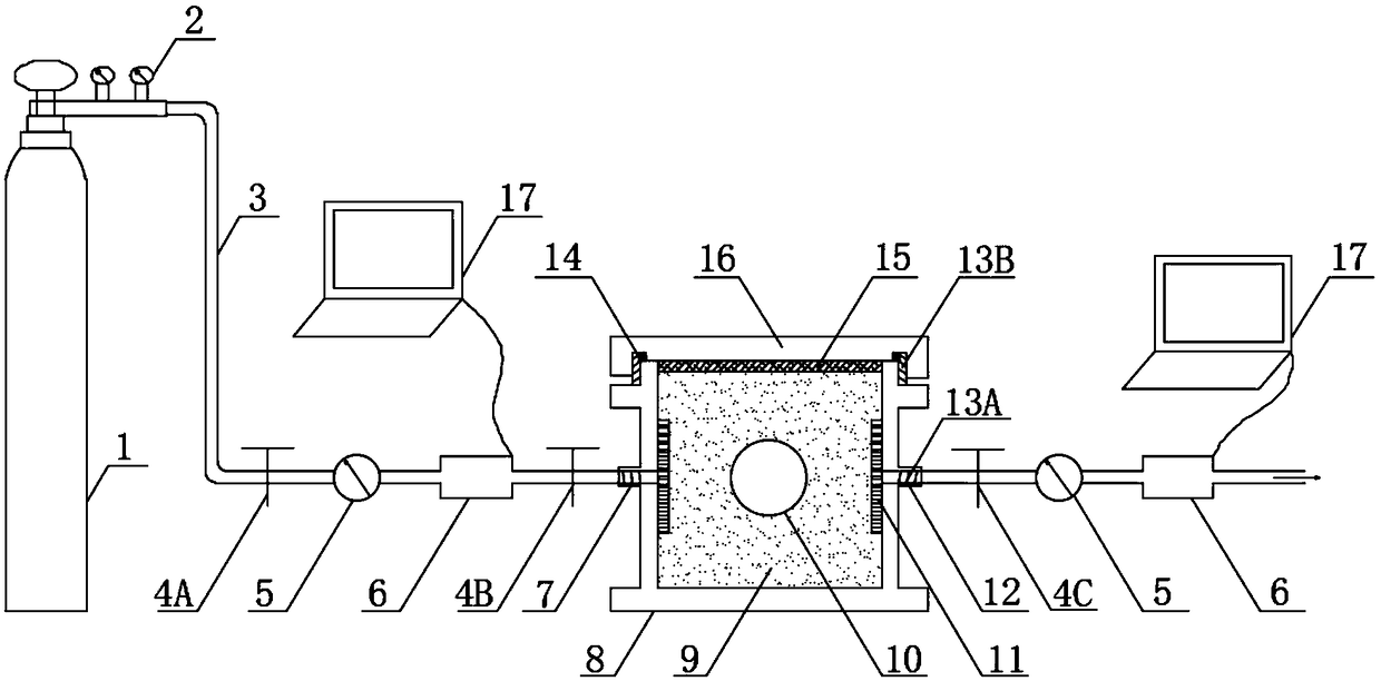
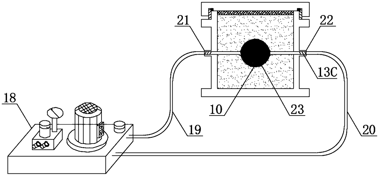
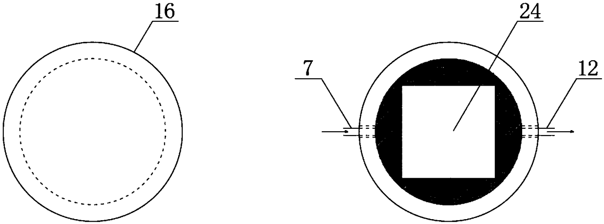
The invention discloses a sealing cavity-based gas experiment device and experiment method for continuous pressure increasing and relief. The device comprises a sealing cavity, a loading and unloadingdevice, a gas supply and control system and a gas flowing quantity dynamic monitoring and data acquisition system, wherein the sealing cavity is of an outer-circle and inner-square cylindrical structure, a cuboid inner cavity is dug in a cylinder and comprises a cuboid inner acvity, a sealing cover, an air inlet, an air outlet, an oil inlet, an oil discharging hole and a steel plate cushion layer, the loading and unloading device comprises an electric control hydraulic pump station, an oil pipe and an elastic hydraulic oil cavity and is used for changing coal pressure by controlling oil supply quantity of the elastic hydraulic oil cavity, and the gas supply and control system, the gas flowing quantity dynamic monitoring system and the air inlet and the air outlet of the sealing cavity areconnected by a steel gas pipeline. By the device, the internal structure change condition and the gas flowing characteristic can be simulated when pressure around coil is changed, and a theoretical support is provided for mining a mine protection layer and improving relieved gas extraction efficiency.
Description
technical field [0001] The invention relates to the technical fields of mine protective layer mining and gas drainage. Background technique [0002] Most coal seams in my country have the characteristics of poor air permeability, low gas pressure, and strong gas adsorption capacity of coal seams. It is difficult and inefficient to directly extract coal seam gas under the condition of low coal seam permeability. Coal seam pressure is an important factor affecting the development of coal seam pores and fissures and the level of permeability. At present, it is one of the effective methods to solve the gas threat and improve the efficiency of gas drainage to change the internal pore and fissure structure of the coal body and improve the permeability of the coal seam through external dynamic action to relieve the pressure of the original coal seam. However, the effect of gas pressure inside the coal body on the development of pores and fissures cannot be ignored. After the press...
Claims
Login to View More Application Information
Patent Timeline
 IPC IPC(8): G01N7/00G01N11/00
CPCG01N7/00G01N11/00
Inventor 赵洪宝李金松张欢黄奕凡王宏冰王建国
Owner CHINA UNIV OF MINING & TECH (BEIJING)
Features
- R&D
- Intellectual Property
- Life Sciences
- Materials
- Tech Scout
- Unparalleled Data Quality
- Higher Quality Content
- 60% Fewer Hallucinations
Learn More Browse by: Latest US Patents, China's latest patents, Technical Efficacy Thesaurus, Application Domain, Technology Topic, Popular Technical Reports.
© 2025 PatSnap. All rights reserved.Legal|Privacy policy|Modern Slavery Act Transparency Statement|Sitemap|About US| Contact US: help@patsnap.com