
Method and device for calculating dynamic equivalent internal resistance

An equivalent internal resistance and dynamic technology, applied in measuring devices, measuring resistance/reactance/impedance, instruments, etc., can solve problems such as rising costs, interference, and prone to misjudgment, so as to reduce misjudgment, avoid irrelevant interference, The effect of avoiding external interference

Active Publication Date: 2018-11-30
浙江长兴笛卡尔科技有限公司
View PDF12 Cites 2 Cited by
  • Summary
  • Abstract
  • Description
  • Claims
  • Application Information

AI Technical Summary

Problems solved by technology

[0004] In order to overcome the deficiencies of the prior art, the object of the present invention is to provide a method and device for calculating the dynamic equivalent internal resistance, aiming at solving the problems that are prone to errors in the process of detecting the details of the action of the device that uses electromagnetic force to achieve mechanical action in the prior art. Judgment, or the introduction of external interference and rising costs

Method used


Image

  • Method and device for calculating dynamic equivalent internal resistance
  • Method and device for calculating dynamic equivalent internal resistance

Examples


specific Embodiment 1

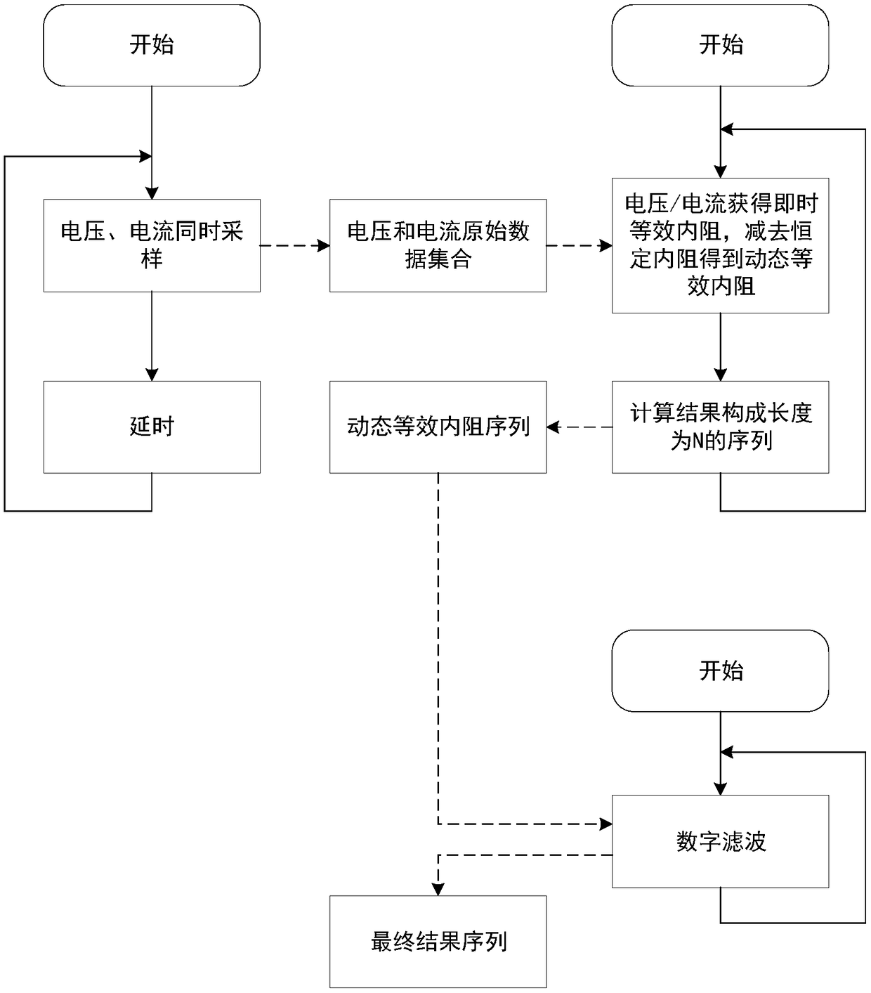
[0034] Based on the concept of battery equivalent internal resistance in the prior art, the embodiment of the present invention expands the concept of dynamic equivalent internal resistance, and the instant equivalent internal resistance and constant resistance are involved in the process. Instantaneous equivalent internal resistance refers to the result obtained by dividing the voltage across the detected object by the current passing through it at a certain moment; constant resistance refers to the resistance formed by the internal resistance of the coil of the detected object, no matter what kind of external interference Such as differential mode interference, its resistance will not change, with strong anti-interference. The dynamic equivalent internal resistance refers to the result obtained by subtracting the constant resistance from the instant equivalent internal resistance.

[0035] The detected object in the embodiment of the present invention refers to an electromag...

specific Embodiment 2

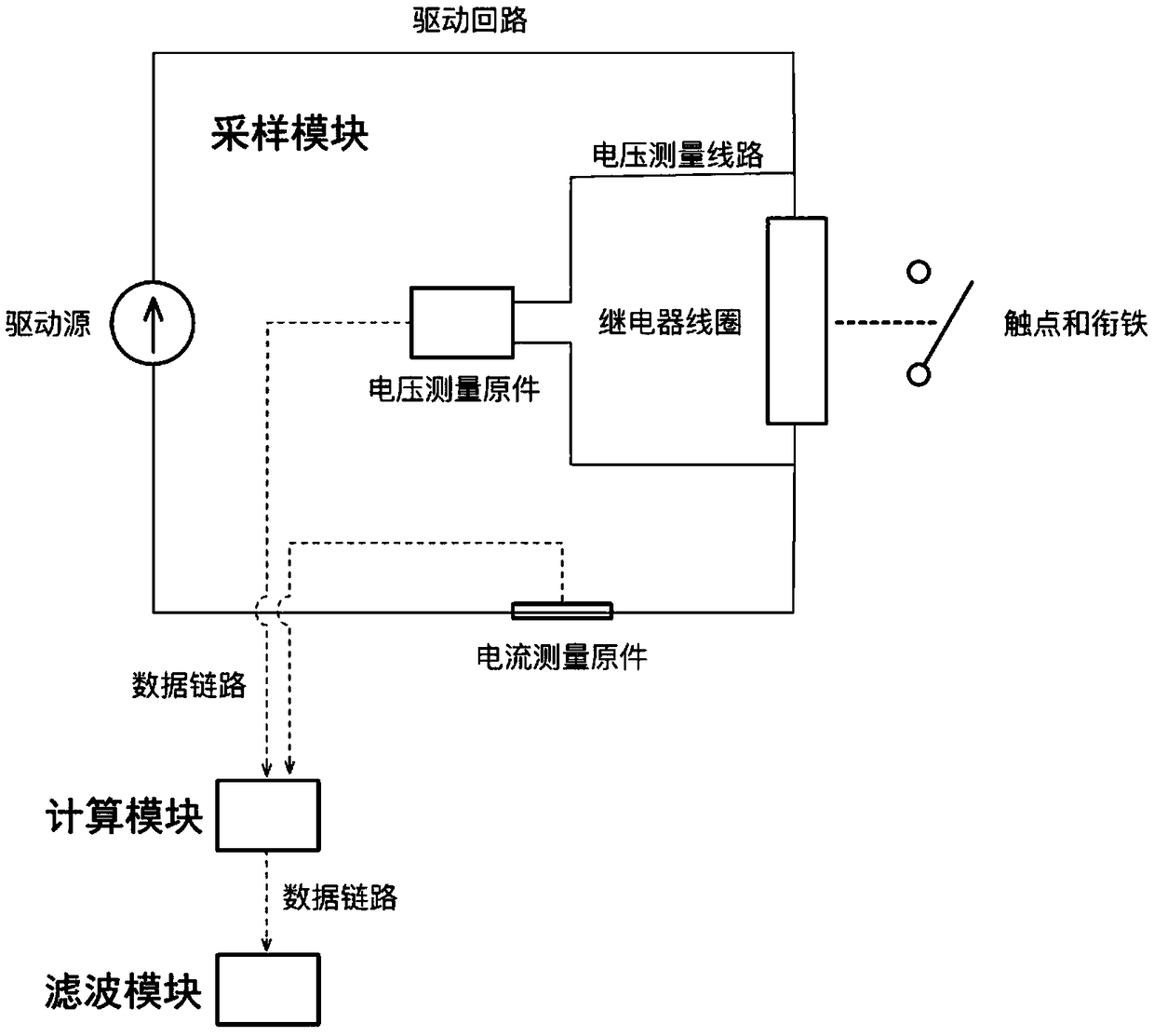
[0046] Such as figure 2 As shown, the embodiment of the present invention provides a device for calculating the dynamic equivalent internal resistance, including an acquisition module and a calculation module connected in sequence, wherein:

[0047] The obtaining module is used to obtain the voltage sampling data and current sampling data of the detected object at the same time;

[0048] The calculation module is used to divide the voltage sampling data by the current sampling data at the same time to obtain the real-time equivalent internal resistance of the detected object at that time; subtract the constant internal resistance from the real-time equivalent internal resistance to obtain the The dynamic equivalent internal resistance.

[0049] The embodiments of the present invention use the input voltage and current data to obtain the instantaneous equivalent internal resistance of the detected object, and subtract the part of the constant internal resistance to calculate ...


PUM


Abstract

The invention discloses a method and device for calculating dynamic equivalent internal resistance. The method for calculating the dynamic equivalent internal resistance comprises the steps that obtaining is carried out, specifically, voltage sampling data and current sampling data of a detected object at the same time are obtained; and calculation is carried out, specifically, the voltage sampling data are divided by the current sampling data at the same time to obtain instant equivalent internal resistance of the detected object at the time, and the dynamic equivalent internal resistance ofthe detected object at the time is obtained by subtracting constant internal resistance from the instant equivalent internal resistance. According to the method and device for calculating the dynamicequivalent internal resistance, the instant equivalent internal resistance of the detected object is obtained by using the input voltage and current data, the dynamic equivalent internal resistance can be obtained by subtracting the constant internal resistance from the instant equivalent internal resistance, and since no additional sensor is led in, external interference caused by the additionalsensor is avoided. Preferably, the dynamic equivalent internal resistance can further be filtered to obtain desired high frequency components, irrelevant interference brought by the environment is avoided while the cost is reduced, and the situation of misjudgment is reduced.

Description

technical field [0001] The invention relates to a mechanical device applying electromagnetic force, in particular to a method and device for calculating the dynamic equivalent internal resistance of the mechanical device applying electromagnetic force. Background technique [0002] There are currently two methods for detecting the action details of electromagnetic relays and / or similar devices that use electromagnetic force to achieve mechanical actions such as electromagnetic valves. One is to directly collect the electromotive force and / or current changes, and then infer the details of the action; the second is to add sensors such as magnetic detectors or pickups, etc., to infer the details of the action through the sensing quantity. [0003] The disadvantage of the first method is that it is very easy to misjudgment in harsh environments (such as automotive environments, complex electromagnetic environments); and the second method inevitably needs to face the external in...

Claims


Application Information

Patent Timeline
Patent Type & Authority Applications(China)
IPC IPC(8): G01R27/08
CPCG01R27/08
Inventor 马瑞
Owner 浙江长兴笛卡尔科技有限公司
Learn More