
Optical fiber wire managing equipment

A technology of cable management equipment and optical fiber, applied in the direction of fiber mechanical structure, etc., can solve the problems of consuming a lot of energy, clearly distinguishing pigtails, and affecting work efficiency, so as to achieve straight and beautiful wiring, improve work efficiency, and facilitate operation Effect

Pending Publication Date: 2018-11-30
STATE GRID CORP OF CHINA +1
View PDF7 Cites 5 Cited by
  • Summary
  • Abstract
  • Description
  • Claims
  • Application Information

AI Technical Summary

Problems solved by technology

At present, the method of bundling the pigtails into bundles can only fix the pigtails at the most basic level, so that they can be neatly arranged in bundles with the direction of the rack, but it is difficult to quickly and clearly distinguish each pigtail. As far as the tail fiber protection work is concerned, it takes a lot of energy and time for the staff to complete it, which seriously affects the work efficiency

Method used


Image

  • Optical fiber wire managing equipment
  • Optical fiber wire managing equipment
  • Optical fiber wire managing equipment

Examples


Embodiment Construction

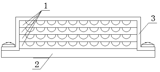
[0023] Below in conjunction with the accompanying drawings, the implementation of the fiber optic cable management device will be further described in detail (see Figure 1-8 ):

[0024] An optical fiber cable management device, which is composed of a pigtail placement plate 1, a fixed frame cover 2, and a base 3; The anastomotic cover is equipped with a fixed frame cover 2, and the fixed frame cover 2 is fixed on the base 3 through bolts;

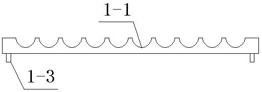
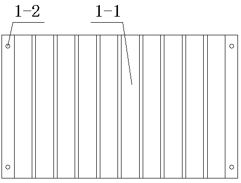
[0025] There are multiple pigtail fiber placement boards 1, and multiple grooves 1-1 are made parallel and evenly distributed on the surface of the pigtail fiber placement board 1. The four corners of the pigtail fiber placement board 1 are symmetrically made with pits A1-2, and the pigtail fiber placement boards The four corners on the back of board 1 are symmetrically made with inserting protrusions A1-3, which correspond to the recesses A1-2 (see Figure 1~3 );

[0026] The fixed frame cover 2 is made up of top plate 2-1, vertical pl...


PUM


Abstract

The invention relates to optical fiber wire managing equipment, and belongs to the technical field of power auxiliary equipment. The optical fiber wire managing equipment is composed of tail fiber placement boards, a fixing frame cover and a base, wherein the tail fiber placement boards are installed on the base in an inserting mode, the fixing frame cover is installed on the tail fiber placementboards in a fit covering mode, and the fixing frame cover is fixedly installed on the base through bolts; multiple grooves are uniformly formed in the tail fiber placement boards in parallel, pits A are symmetrically formed in the four corners of the upper faces of the tail fiber placement boards, inserting protrusions A are symmetrically arranged at the four corners of the back faces of the tailfiber placement boards, and the inserting protrusions A corresponds to the pits A; the fixing frame cover is composed of a top plate, vertical plates and transverse plates; inserting protrusions B aresymmetrically arranged at the four corners of the lower face of the top plate, and bolt holes are formed in the transverse plates; the base is composed of a convex plate and side plates, the side plates are symmetrically arranged on the left and right sides of the convex plate, and thread pits are formed in the side plates; pits B are symmetrically formed in the four corners of the upper face ofthe convex plate, and the tail fiber placement boards are connected with the base through the inserting protrusions A and the pits B in a plug-in mounting mode. According to the optical fiber wire managing equipment, the tail fiber can be quickly arranged and exchanged, and the head and tail ends of the tail fiber are clear and distinguishable; and routing is straight, both time and labour are saved, and the work efficiency is high.

Description

technical field [0001] The invention relates to an optical fiber cable management device, which belongs to the technical field of electric power auxiliary devices. Background technique [0002] The power communication system needs to use a large number of pigtails. According to statistics, the amount of pigtails used in each communication room is about 200 to 400. The daily maintenance of pigtails includes: cleaning out the pigtails from the wire slot, laying new pigtails in the wire slot, checking the head and end of each pigtail, etc.; the workload of the staff to maintain the pigtails It can be seen that it is so big and complicated to operate. At present, the method of bundling the pigtails into bundles can only fix the pigtails at the most basic level, so that they can be neatly arranged in bundles with the direction of the rack, but it is difficult to quickly and clearly distinguish each pigtail. For the tail fiber protection work, it needs the staff to expend consid...

Claims


Application Information

Patent Timeline
Patent Type & Authority Applications(China)
IPC IPC(8): G02B6/44
CPCG02B6/44
Inventor 邱磊张文军杨萍吴卫洪陈德威马开宇李涛陈雪韩理达李颖王雄孟欣肖潇
Owner STATE GRID CORP OF CHINA
Learn More