Fingerprint identification device

A fingerprint recognition and fingerprint recognition module technology, applied in character and pattern recognition, instruments, computer parts, etc., can solve the problems of inability to recognize, waste energy, and low recognition efficiency, and achieve the effect of saving electricity and improving efficiency.

Inactive Publication Date: 2018-11-30
孟超
View PDF0 Cites 3 Cited by
  • Summary
  • Abstract
  • Description
  • Claims
  • Application Information

AI Technical Summary

Problems solved by technology

The difference shows that the user's fingers are too dry or too wet or dusty will affect the recognition performance of the fingerprint recognition module. The existing fingerprint recognition devices usually have low recognition efficiency or no recognition. It can be tried many times, the efficiency of fingerprint recognition is low, and the fingerprint recognition device is usually used for a specific period of time, which wastes energy when it is not used for a long time

Method used


Image

  • Fingerprint identification device
  • Fingerprint identification device
  • Fingerprint identification device

Examples


Embodiment 1

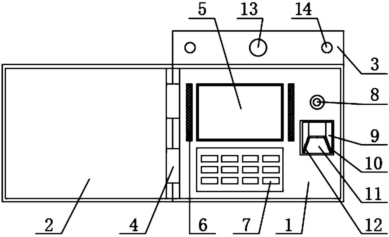
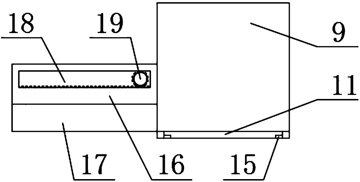
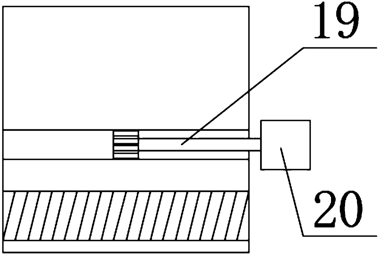
[0025] Such as Figure 1-4 The fingerprint identification device shown includes a device body 1, a cover plate 2 and a mounting seat 3, a damping hinge 4 is installed on the left side of the device body 1, and the two ends of the damping hinge 4 are respectively fixed to the device body 1 and the cover plate 2 connection, the upper end of the device body 1 is fixed with a mounting seat 3, a display screen 5 is installed on the device body 1, a speaker 6 is installed outside the display screen, and a setting button 7 is installed at the lower end of the display screen 5. A camera 8 is installed on the right side of the speaker 6, a first groove 9 is installed at the lower end of the camera 8, a dust sensor 10 is installed at the bottom of the first groove 9, a fingerprint recognition module 11 is installed on the left side of the dust sensor 10, A humidity sensor 12 is installed on the left side of the fingerprint identification module 11, an infrared sensing module 13 is insta...

Embodiment 2

[0030] Such as Figure 5 As shown, the difference between this embodiment and Embodiment 1 is that the lower end of the first groove 9 is provided with a second groove 23, and absorbent paper 24 is installed in the groove 23 to prevent fingers from getting dirty or wet. There is no paper towel on the body so that the fingerprint cannot be recognized in time, and one end of the absorbent paper 24 is fixedly connected to the inside of the second groove 23 by glue, which is convenient for successive use.

[0031] The working principle is as follows: install the fingerprint identification device in a suitable position through the installation hole 14 on the mounting base 3 and turn on the power, open the cover 2 when identifying the fingerprint, and put the finger into the first groove through the setting button 7 and the display screen 5 The fingerprint identification module 11 in 9 is identified, and the dust sensor 10, the humidity sensor 12 and the pressure sensor 15 cooperate...


PUM


Abstract

The invention relates to a fingerprint identification device, and belongs to the technical field of fingerprint identification. The fingerprint identification device comprises a device body, a cover plate and a mounting base; the device body is connected with the cover plate through a damping hinge; the mounting base is fixed at the upper end of the device body; a display screen, a loudspeaker, asetting button, a camera and a first groove are mounted on / in the device body; a dust sensor, a fingerprint identification module and a humidity sensor are mounted at the bottom of the first groove; and the mounting base is provided with an infrared sensing module and a mounting hole. The dust sensor, the humidity sensor and a pressure sensor cooperate with a control chip and a voice module; the reason for the situation that a fingerprint cannot be identified is judged and is prompted by the loudspeaker, so that identification personnel can perform adjustment in time, and the fingerprint identification efficiency is improved; and when no person exists in a certain time, the control chip controls the device to be automatically switched off, so that electricity is saved.

Description

technical field [0001] The invention relates to the technical field of fingerprint identification, in particular to a fingerprint identification device. Background technique [0002] Fingerprint refers to the uneven lines on the front skin of the finger end of a person. Due to its lifelong invariance, uniqueness and convenience, it has almost become synonymous with biometric identification. Fingerprint identification refers to the comparison of the details of different fingerprints. Click to identify. [0003] Before using the fingerprint recognition smart device, the user needs to pre-enter the fingerprint in the smart device, and then compare the fingerprint recognition with the fingerprint in the fingerprint library again for unlocking, attendance check-in, etc., which are more and more applied to people's life and work. The difference shows that the user's fingers are too dry or too wet or dusty will affect the recognition performance of the fingerprint recognition modu...

Claims


Application Information

Patent Timeline
Patent Type & Authority Applications(China)
IPC IPC(8): G06K9/00
CPCG06V40/13
Inventor 孟超
Owner 孟超
Why Eureka
Try Eureka