Over-current protection self-locking circuit and air conditioner

A technology of self-locking circuit and over-current protection, applied in emergency protection circuit devices, electrical components, etc., can solve the problems that the PWM signal cannot be turned off, and the MCU cannot effectively detect the protection signal, so as to avoid repeated wear and tear and prolong the service life , the effect of protecting the motor

Active Publication Date: 2018-11-30
珠海拓芯科技有限公司
View PDF7 Cites 1 Cited by
  • Summary
  • Abstract
  • Description
  • Claims
  • Application Information

AI Technical Summary

Problems solved by technology

[0003] In practical applications, after the overcurrent protection occurs, the hardware drive circuit immediately shuts off the drive output of the power module, the motor stops immediately, the high current disappears immediately, and the protection signal of the overcurrent protection circuit also disappears immediately, which will cause the MCU to fail to detect The protection signa

Method used


Image

  • Over-current protection self-locking circuit and air conditioner
  • Over-current protection self-locking circuit and air conditioner
  • Over-current protection self-locking circuit and air conditioner

Examples


no. 1 example

[0029] This embodiment provides an over-current protection self-locking circuit 1. After the over-current protection is triggered so that the hardware driver module 5 stops driving the power module 4, the over-current protection self-locking circuit 1 can continuously output fault signals, so that the processor 6 can detect the fault signal, so as to implement a more complete protection action.

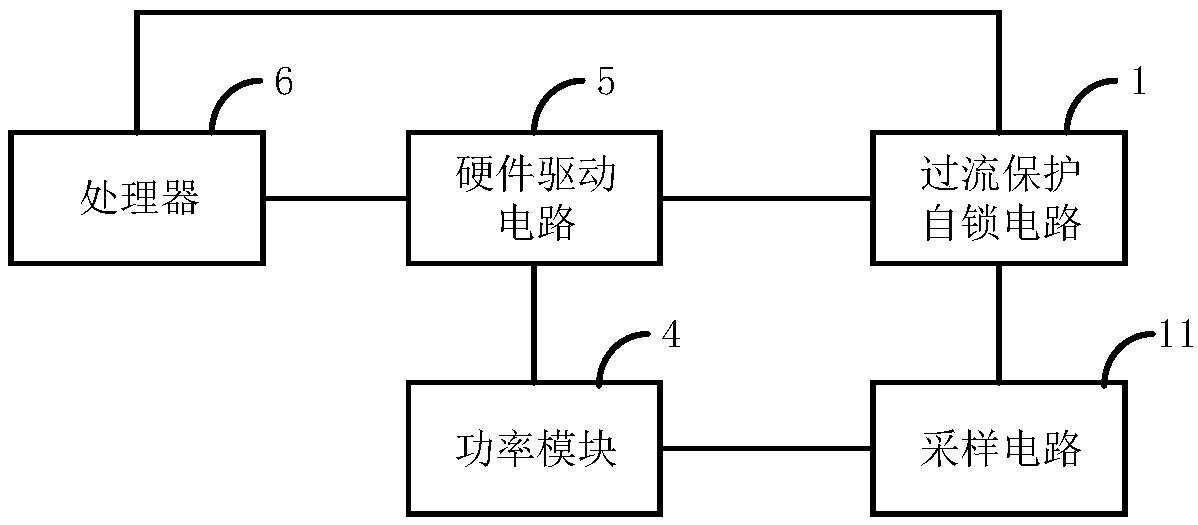
[0030] see figure 1 , figure 1 A schematic diagram of an application scenario of the overcurrent protection self-locking circuit 1 provided in this embodiment is shown, the overcurrent protection self-locking circuit 1 is electrically connected to a power module 4, and the overcurrent protection self-locking circuit 1 is also connected to a hardware The drive module 5 is electrically connected, and the hardware drive module 5 is electrically connected with the power module 4 to drive the power module 4; the overcurrent protection self-locking circuit 1 includes: a first signal proces...

no. 2 example

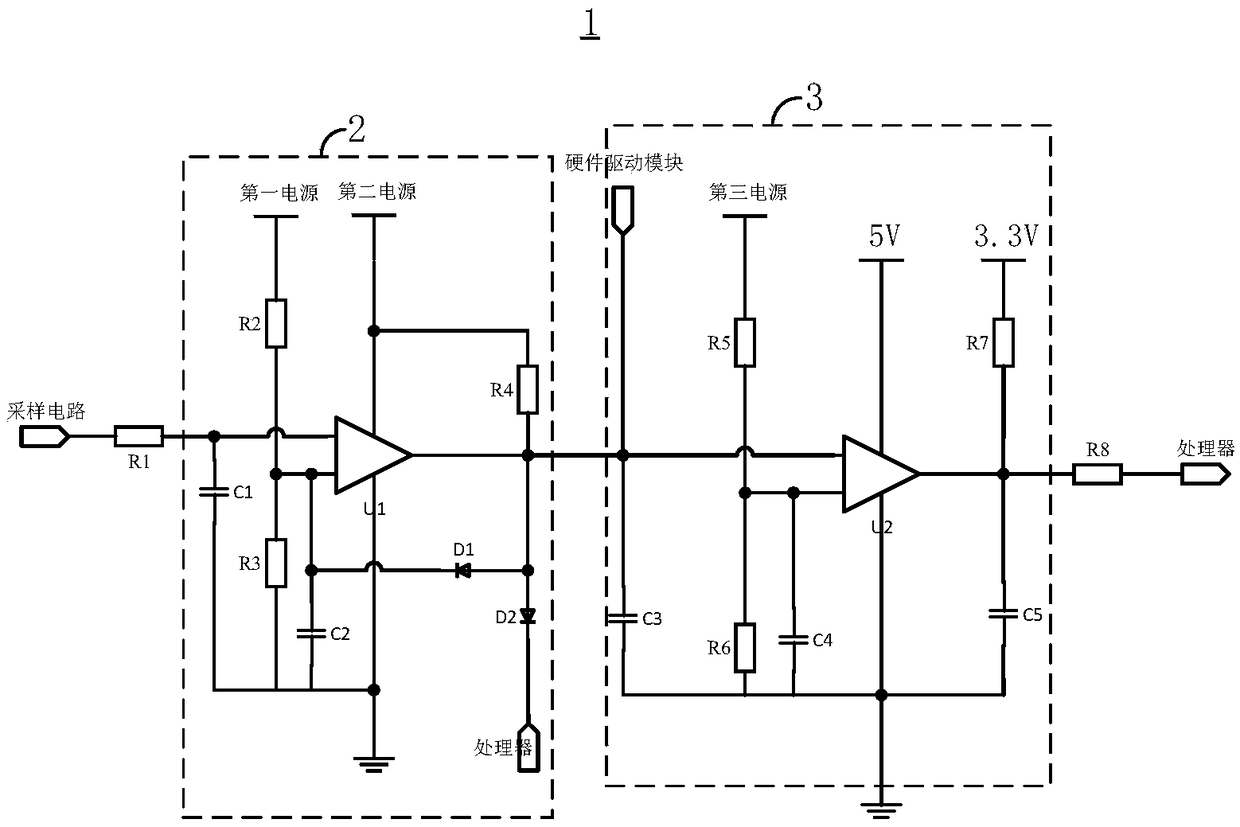
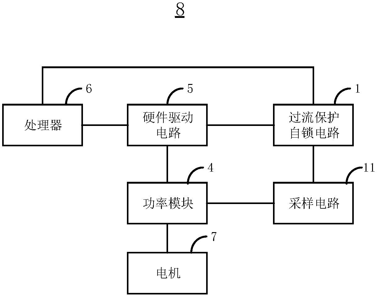
[0052] This embodiment provides an air conditioner 8, please refer to image 3 , the air conditioner 8 includes a processor 6, a hardware driver module 5, a power module 4, a motor 7 and the overcurrent protection self-locking circuit 1 provided in the first embodiment, the processor 6 and the hardware driver module 5 Electrically connected, the hardware driver module 5 is electrically connected to the power module 4 , and the power module 4 is electrically connected to the motor 7 . The overcurrent protection self-locking circuit 1 includes a first signal processing module 2 and a second signal processing module 3, the first signal processing module 2 is electrically connected to the power module 4 through a sampling circuit 11, and the first signal processing module 2 is electrically connected to the power module 4 through a sampling circuit 11. The output terminal of the processing module 2 is electrically connected to the second signal processing module 3 , and the output ...


PUM


Abstract

The invention provides an over-current protection self-locking circuit and an air conditioner. By arranging a voltage changing unit, a first comparator can be enabled to maintain the relative state ofthe level of a same-phase input terminal and the level of an anti-phase input terminal after becoming a first level signal through over-current protection by high-current trigger, so that the level state of an output terminal of the first comparator is maintained, and a processor can detect an overvoltage or over-current protection signal in time so as to implement protection to protect a motor.The over-current protection self-locking circuit avoids the situation that repeated loss of a power module is prone to occurring in a traditional over-current protection circuit, and the motor can beeffectively protected, and the service life of the motor and the service life of the air conditioner are prolonged.

Description

technical field [0001] The invention relates to the technical field of overcurrent protection, in particular to an overcurrent protection self-locking circuit and an air conditioner. Background technique [0002] The motor is an important part of the air conditioner. In order to avoid damage to the power module device or the motor due to overcurrent in the motor, an overcurrent protection circuit is usually installed between the existing hardware drive circuit and the power module. At the same time, the overcurrent protection circuit is connected with a micro control unit (MicrocontrollerUnit, MCU). The specific working process of the overcurrent protection is: the sampling module samples the voltage signal of the power module and outputs it to the overcurrent protection circuit after amplifying. When the voltage signal is detected to be higher than the set value of the protection point, the overcurrent protection circuit generates a protection signal Output to the hardware...

Claims


Application Information

Patent Timeline
IPC IPC(8): H02H7/085
Inventor 李超游剑波
Owner 珠海拓芯科技有限公司
Why Eureka
Try Eureka