
Signal multiplexing circuit and method

A signal multiplexing and circuit technology, applied in the direction of logic circuit connection/interface layout, etc., can solve problems such as difficult to meet product space restrictions and large space restrictions, achieve small-scale size, reduce PIN pins, and meet space restrictions required effect

Active Publication Date: 2020-08-11
GUANGDONG VTRON TECH CO LTD
View PDF3 Cites 0 Cited by
  • Summary
  • Abstract
  • Description
  • Claims
  • Application Information

AI Technical Summary

Problems solved by technology

[0002] Under the trend of high integration of existing electronic products, the application of signal multiplexing technology in electronic products is increasing. It is difficult to meet the space restriction requirements of the product when implementing the signal multiplexing function

Method used


Image

  • Signal multiplexing circuit and method
  • Signal multiplexing circuit and method
  • Signal multiplexing circuit and method

Examples


Embodiment Construction

[0045] Under the trend of high integration of existing electronic products, the application of signal multiplexing technology in electronic products is increasing. When implementing the signal multiplexing function, it is difficult to meet the space limitation requirements of the product. The inventors found through investigation that the main reason why the existing technology is difficult to meet the space limitation requirements is that multiple signal lines are used to realize the signal multiplexing function, which leads to the connector's The large size of the PIN pin may not be installed between various boards. For example, a connector with a large size is difficult to be installed between the power supply board and the main control board.

[0046] The defects in the solutions in the above prior art are all the results obtained by the inventor after practice and careful research. Therefore, the discovery process of the above problems and the solutions to the above proble...


PUM


Abstract

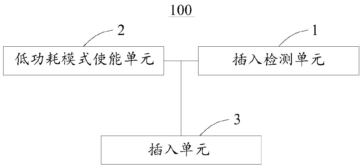
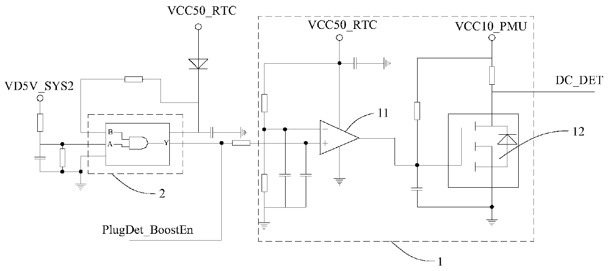
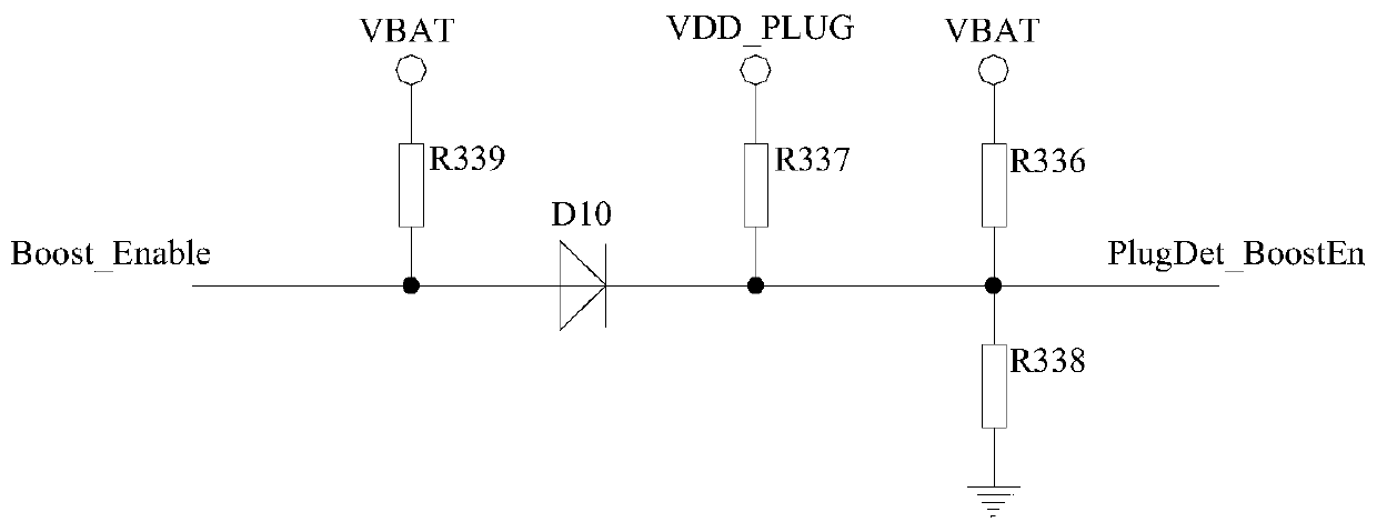
Embodiments of the present invention relate to the technical field of electronic products, and in particular, to a signal multiplexing circuit and method. The signal multiplexing circuit includes an insertion detection unit, an insertion unit and a low power consumption mode enabling unit, the insertion detection unit and the low power consumption mode enabling unit are respectively connected to the insertion unit, and the insertion detection unit is used to receive the multiplexing signal sent by the insertion unit signal, and compare the obtained set voltage with the voltage of the multiplexed signal to obtain the comparison result, and input the corresponding level signal to the switch according to the comparison result, and the switch is used to adjust its own working state according to the level signal to realize Different detection signal output. The low power consumption mode enabling unit is used to adjust the multiplexed signal, and the insertion unit is used to control the working state of the external booster line according to the adjusted multiplexed signal. The signal multiplexing circuit can meet the space restriction requirements of the product on the premise of realizing the signal multiplexing function.

Description

technical field [0001] Embodiments of the present invention relate to the technical field of electronic products, and in particular, to a signal multiplexing circuit and method. Background technique [0002] Under the trend of high integration of existing electronic products, the application of signal multiplexing technology in electronic products is increasing. It is difficult to meet the space restriction requirements of the product when realizing the signal multiplexing function. Contents of the invention [0003] In view of this, the present invention provides a signal multiplexing circuit and method, which can meet the space restriction requirements of products on the premise of realizing the signal multiplexing function. [0004] To achieve the above object, an embodiment of the present invention provides a signal multiplexing circuit, including: an insertion detection unit, an insertion unit, and a low power consumption mode enabling unit; the insertion detection u...

Claims


Application Information

Patent Timeline
Patent Type & Authority Patents(China)
IPC IPC(8): H03K19/0175
CPCH03K19/0175
Inventor 朱彦
Owner GUANGDONG VTRON TECH CO LTD
Learn More