Panoramic camera monitoring device capable of automatically removing dust through gas

A panoramic camera and automatic dust removal technology, applied in the field of surveillance cameras, can solve the problems of easy dusting of monitors, scratches and blurred lenses, etc., and achieve the effect of preventing dead ends of monitoring, reducing wiping, and reducing the impact of the environment.

Inactive Publication Date: 2018-11-30
四川知创知识产权运营有限公司
View PDF0 Cites 7 Cited by
  • Summary
  • Abstract
  • Description
  • Claims
  • Application Information

AI Technical Summary

Problems solved by technology

[0003] The technical problem to be solved by the present invention is: in the dusty environment of the factory, the monitor is easily stained with dust, and the lens is easily scratched and blurred when the lens is often wiped. The present invention provides a solution to the above problems. Panoramic camera monitoring device for gas automatic dust removal

Method used


Image

  • Panoramic camera monitoring device capable of automatically removing dust through gas

Examples


Embodiment 1

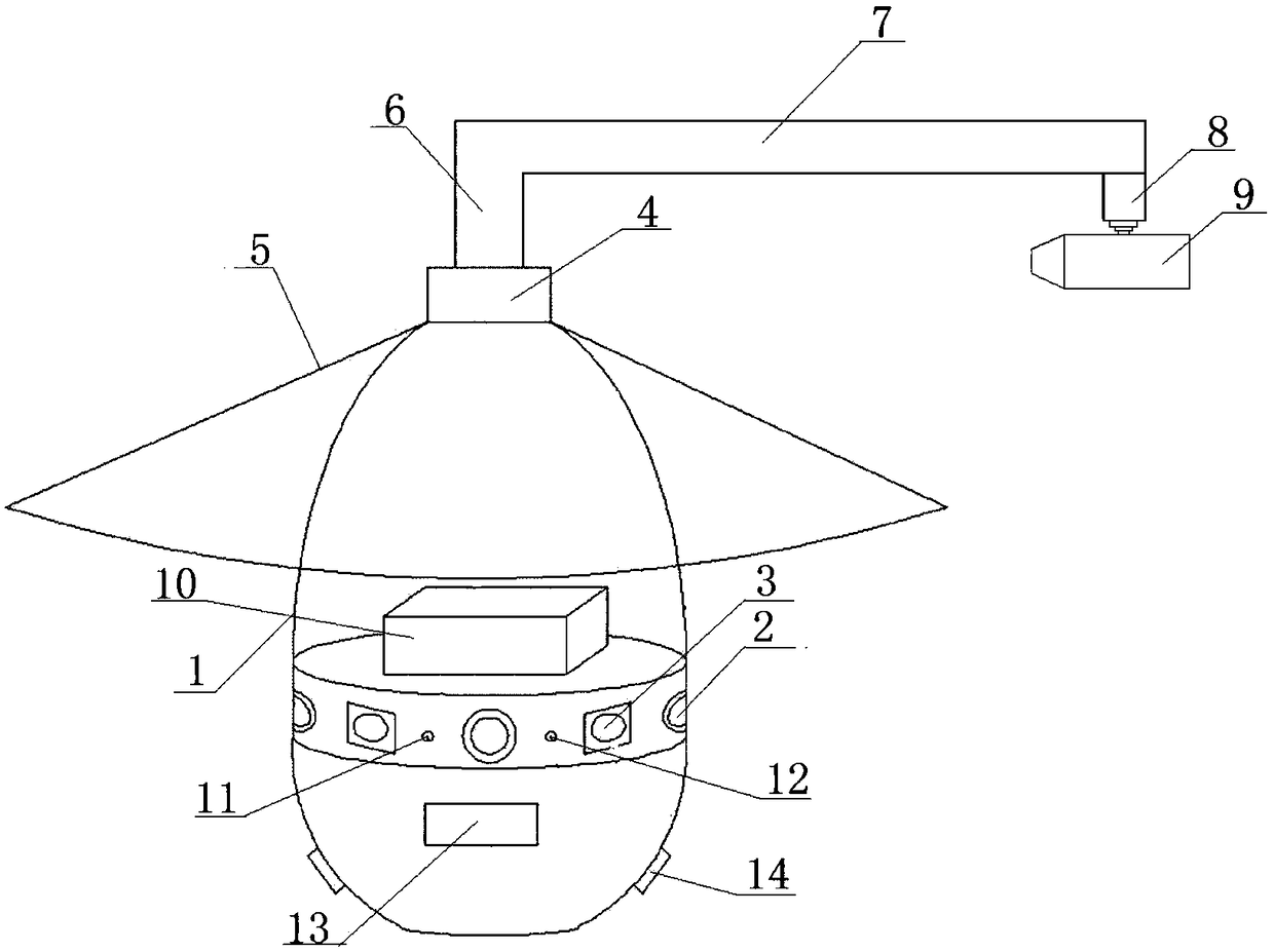
[0021] Such as figure 1 As shown, the panoramic camera monitoring device for automatic gas dust removal includes a main frame 1, a fisheye camera 2 and an infrared camera 3, wherein the main frame 1 is an upright ellipse, and the fisheye camera 2 and the The infrared camera 3 is staggered around the middle part of the main frame 1, the top of the main frame 1 is equipped with a connecting piece 4, the surrounding of the connecting piece 4 is sealed with an umbrella cover 5, and the connecting piece 4 is rotatably installed with Rotating rod 6, control motor is installed in the top of described main frame 1, and described control motor is rotated with control rotating rod 6, and the other end of described rotating rod 6 is vertically welded with connecting rod 7, and the other end of described connecting rod 7 An electric push rod 8 is welded vertically below the electric push rod 8, and a blower 9 is fixedly installed on the electric push rod 8. A control center 10 is arranged...

Embodiment 2

[0023] Such as figure 1 As shown, the difference between this embodiment and Embodiment 1 is that the angle between the fisheye camera 2 and the infrared camera 3 is 60°. The angle of each rotation of the rotating rod 6 controlled by the control motor is 60°. A first indicator light 11 and a second indicator light 12 are also provided on the upper part of the main body frame 1 . The lower part of the main frame 1 is provided with a photosensitive sensor 13 and a pickup 14 . Both the first indicator light 11 and the second indicator light 12 are electrically connected to the control center 10 .


PUM


Abstract

The invention discloses a panoramic camera monitoring device capable of automatically removing dust through gas, and solves the problem that a lens is easily scratched and blurred due to the fact thatthe lens is frequently wiped when the monitor is easily dusted in environments having much dust, such as a factory. The panoramic camera monitoring device in the invention comprises a main frame, a fisheye camera and an infrared camera; the main frame is a vertical oval; the fisheye camera and the infrared camera are staggered and encircled in the middle of the main frame; a connecting part is installed on the top of the main frame; an umbrella cover is installed around the connecting part in a sealed manner; a rotary rod is rotatably installed on the connecting part; a control motor is installed in the top of the main frame; the control motor controls the rotary rod to rotate; a connecting rod is vertically welded on the other end of the rotary rod; an electric push rod is vertically welded below the other end of the connecting rod; an air blower is fixedly installed on the electric push rod; a control centre is arranged in the main frame; and the air blower is connected with the control centre through a conductor wire.

Description

technical field [0001] The invention relates to a monitoring camera, in particular to a panoramic camera monitoring device for automatic gas dust removal. Background technique [0002] With the continuous development of society, video surveillance plays an increasingly important role in ensuring public safety and maintaining social stability. In the security of public places such as squares, roads, shopping malls, and residential areas, it is necessary to carry out comprehensive monitoring of the entire environment. For monitoring, the traditional method is to install multiple cameras with different shooting angles on site. However, due to the wide range of monitoring targets, even if multiple cameras are installed, it is impossible to achieve monitoring without dead ends, and this method has high cost and failure rate. high as the title. With the development of computer technology, computer image processing and image synthesis technology are becoming more and more mature. ...

Claims


Application Information

Patent Timeline
Patent Type & Authority Applications(China)
IPC IPC(8): H04N5/225H04N7/18H04N5/232B08B13/00B08B5/02
CPCH04N7/18B08B5/02B08B13/00H04N23/00H04N23/60
Inventor 黄欢
Owner 四川知创知识产权运营有限公司
Why Eureka
Try Eureka