

Caster rack
A technology for seasoning bottles and seasonings, which is applied in the directions of home appliances, applications, kitchen appliances, etc., can solve the problems of inconvenient use, crowded kitchen, unfavorable kitchen arrangement and cleaning, etc.
Inactive Publication Date: 2018-12-04
李侨艳
View PDF0 Cites 0 Cited by
- Summary
- Abstract
- Description
- Claims
- Application Information
AI Technical Summary
Problems solved by technology
[0002] The seasoning bottle rack used by people in daily life is usually placed next to the stove, which is not conducive to the organization and cleaning of the kitchen, and it is also inconvenient to use, making the kitchen more crowded
Method used
View moreImage
Smart ImageViewing Examples

Examples
Embodiment Construction
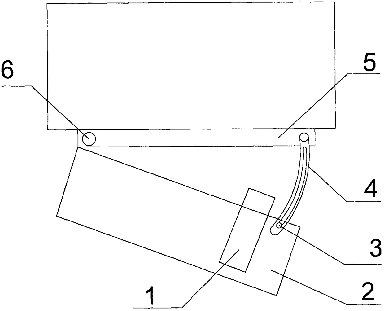
[0010] Such as figure 1 As shown, a convenient invisible seasoning bottle rack, the frame body 2 on which the seasoning bottle 1 is placed has a fixed slider 3, the fixed plate 5 is connected with the arc support 4, and one end of the frame body 2 is placed on the arc through the fixed slider 3. The support 4 slides and is connected with the fixed plate 5 , and the other end of the frame body 2 is connected with the frame body 2 through bolts 6 .
[0011] During use, pull down frame body 1, just can take out the condiment bottle 1 that is placed in frame body 2 li, after using up, push up seasoning bottle frame body 2, seasoning bottle frame body 2 moves up, and seasoning bottle frame closes.
Login to View More PUM
 Abstract
The invention provides a caster rack. For the caster rack, a fixing slider is arranged on a rack body on which a caster is placed, a fixing plate is connected with an arc-shaped support, one end of the rack body slides on the arc-shaped support through the fixing slider to be connected with the fixing plate, and the other end of the rack body is connected with the fixing plate through a bolt. Dueto the adoption of the structure, the caster rack can be opened or closed through the arc-shaped support, so that the caster is hidden in the caster rack, the caster rack is hidden at the bottom of acabinet, and thus the purposes of beautifying a kitchen and saving the space are achieved.
Description
technical field [0001] The invention relates to an improvement of a seasoning bottle rack, in particular to a convenient invisible seasoning bottle rack. Background technique [0002] The seasoning bottle racks that people use in life are usually placed by the stove, which is not conducive to the arrangement and cleaning of the kitchen, and is also inconvenient to use, making the kitchen seem more crowded. Contents of the invention [0003] The object of the present invention is to provide a kind of invisible seasoning bottle rack which can make the seasoning bottle be concealed in the seasoning bottle rack, and the seasoning bottle rack is invisible at the bottom of the cabinet. [0004] The purpose of the present invention is achieved in this way: a convenient invisible seasoning bottle rack, a fixed slider is placed on the frame body where the seasoning bottle is placed, the fixed plate is connected with the arc support, and one end of the frame body is fixed on the arc...
Claims
Login to View More Application Information
Patent Timeline
 IPC IPC(8): A47J47/16
CPCA47J47/16
Inventor 李侨艳
Owner 李侨艳