Ramp running crane

A crane and ramp technology, applied in the direction of cranes, trolley cranes, traveling mechanisms, etc., can solve problems such as tilting of gantry cranes, and achieve the effects of stable operation structure, convenient use and simple structure

Pending Publication Date: 2018-12-04
德马科起重机械有限公司
View PDF0 Cites 0 Cited by
  • Summary
  • Abstract
  • Description
  • Claims
  • Application Information

AI Technical Summary

Problems solved by technology

The gantry crane has the characteristics of high site utilization rate, large operation range, wide adaptability, and strong versatility. It is widely used in port freight yards. Its metal structure is like a door-shaped frame. Two legs are installed under the main beam, which can be directly Walking on the track on the ground, the two ends of the main girder can have outrigger cantilever beams. The gantry cranes in the prior art can only walk on the established track on the plane. The existing gantry crane does not have a gantry crane specially used for walking on the ramp. When the conventional gantry crane is used on the ramp, it will be inclined and cannot be braked, which will affect the use. Therefore, it is necessary to provide a structure Simple, slope-operable, stable-running and easy-to-use ramp-running cranes are necessary

Method used


Image

  • Ramp running crane
  • Ramp running crane
  • Ramp running crane

Examples


Embodiment 1

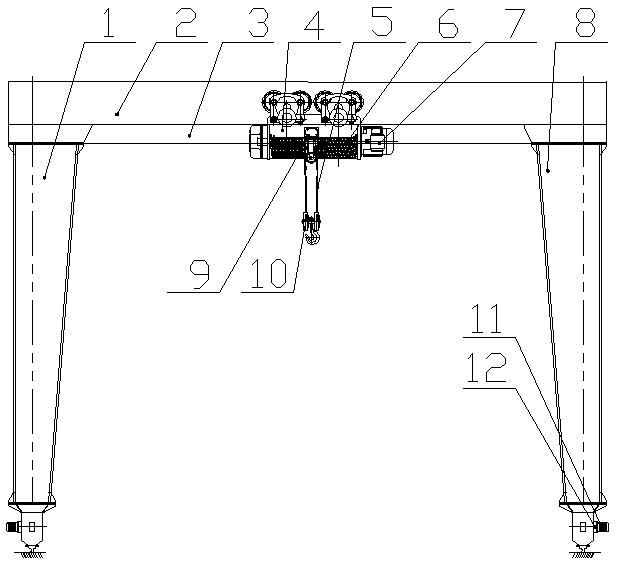
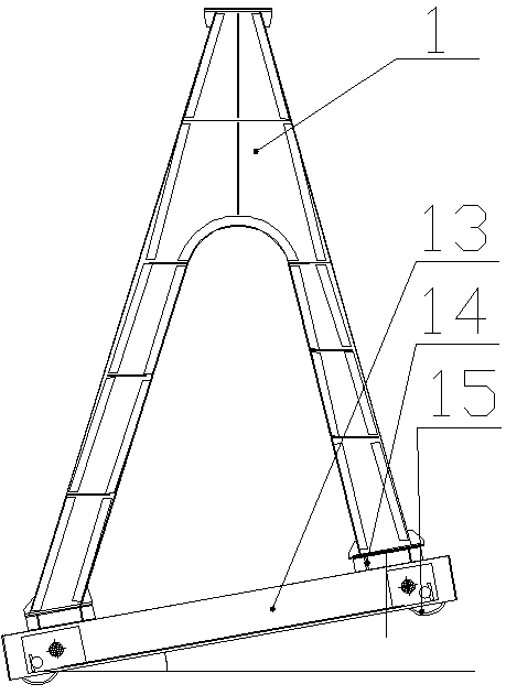
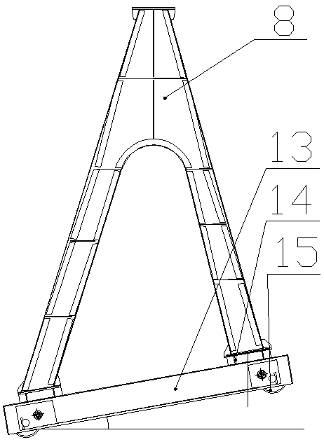
[0017] Such as figure 1 , figure 2 , image 3 , Figure 4 As shown, a crane running on a ramp includes a main beam 2, a left leg 1, a right leg 8 and a bottom beam 13, and the two ends of the main beam 2 are respectively equipped with a left leg 1 and a right leg. Outrigger 8, described main beam 2 is provided with slide rail 3, and described slide rail 3 is provided with elevating device 4, and described elevating device 4 comprises intermediate pulley 9, first motor 7 and reel 6, The two sides of described intermediate pulley 9 are respectively set as reel 6, and the both sides of described reel 6 are set as first motor 7, and described reel 6 is connected with steel wire rope 5, and described two steel wire ropes 5 A spreader 10 is connected together; the shapes of the left outrigger 1 and the right outrigger 8 are both set in the shape of "eight", and the bottom ends of the left outrigger 1 and the right outrigger 8 are provided with bottom beams 13. The two ends of t...

Embodiment 2

[0020] Such as figure 1 , figure 2 , image 3 , Figure 4 As shown, a crane running on a ramp includes a main beam 2, a left leg 1, a right leg 8 and a bottom beam 13, and the two ends of the main beam 2 are respectively equipped with a left leg 1 and a right leg. Outrigger 8, described main beam 2 is provided with slide rail 3, and described slide rail 3 is provided with elevating device 4, and described elevating device 4 comprises intermediate pulley 9, first motor 7 and reel 6, The two sides of described intermediate pulley 9 are respectively set as reel 6, and the both sides of described reel 6 are set as first motor 7, and described reel 6 is connected with steel wire rope 5, and described two steel wire ropes 5 A spreader 10 is connected together; the shapes of the left outrigger 1 and the right outrigger 8 are both set in the shape of "eight", and the bottom ends of the left outrigger 1 and the right outrigger 8 are provided with bottom beams 13. The two ends of t...


PUM


Abstract

The invention relates to a ramp running crane. The ramp running crane comprises a main beam, a left supporting leg, a right supporting leg and bottom beams, the left supporting leg and the right supporting leg are respectively mounted at two ends of the main beam, a sliding rail is arranged on the main beam, a lifting device is mounted on the sliding rail, the lifting device comprises a middle pulley, first motors and a reel, the reel is arranged at two sides of the middle pulley, the first motors are arranged at two sides of the reel, the reel is connected with wire ropes, and the two wire ropes are commonly connected with a suspender; and the shape of each of the left supporting leg and the right supporting leg is an inverted V shape, the bottom beams are arranged at the bottom ends of the left supporting leg and the right supporting leg, wheels are arranged at two ends of every bottom beam, the wheels are fixed by rotating shafts, every rotating shaft is provided with a brake, the output ends of second motors are hinged to the end parts of the rotating shafts, and the rotating shafts are connected with the output ends of the second motors through decelerators. The ramp running crane has the advantages of simple structure, running on a ramp, stable running structure, and convenience in use.

Description

technical field [0001] The invention belongs to the technical field of crane systems, and in particular relates to a ramp-running crane. Background technique [0002] Gantry crane is a deformation of bridge crane, also called gantry crane. It is mainly used for loading and unloading operations of outdoor cargo yards, stockyard cargoes, and bulk cargoes. The gantry crane has the characteristics of high site utilization rate, large operation range, wide adaptability, and strong versatility. It is widely used in port freight yards. Its metal structure is like a door-shaped frame. Two legs are installed under the main beam, which can be directly Walking on the track on the ground, the two ends of the main girder can have outrigger cantilever beams. The gantry cranes in the prior art can only walk on the established track on the plane. The existing gantry crane does not have a gantry crane specially used for walking on the ramp. When the conventional gantry crane is used on the...

Claims


Application Information

Patent Timeline
Patent Type & Authority Applications(China)
IPC IPC(8): B66C19/02B66C5/02B66C9/10B66C9/08
CPCB66C19/02B66C5/02B66C9/08B66C9/10
Inventor 董爱军毛义雪孔纯恒
Owner 德马科起重机械有限公司
Why Eureka
Try Eureka