
A cooling device for small electrical components used in alternating current

A technology for electrical components and heat sinks, which is applied in the field of heat sinks for small electrical components, can solve the problems of unfavorable packaging of cooling fans and the use of some small electronic components.

Active Publication Date: 2020-01-07
江苏森德邦信息科技有限公司
View PDF4 Cites 0 Cited by
  • Summary
  • Abstract
  • Description
  • Claims
  • Application Information

AI Technical Summary

Problems solved by technology

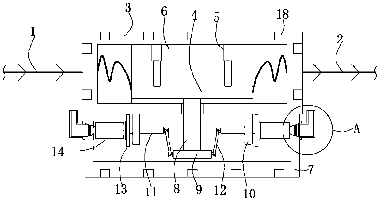
[0004] The purpose of the present invention is to solve the problem that the cooling fan used by electrical appliances can only use direct current, and the large volume of the cooling fan is not conducive to the packaging and the use of some small electronic components, and proposes a cooling device for small electrical components used in alternating current

Method used


Image

  • A cooling device for small electrical components used in alternating current
  • A cooling device for small electrical components used in alternating current
  • A cooling device for small electrical components used in alternating current

Examples


Embodiment Construction

[0020] The technical solutions in the embodiments of the present invention will be clearly and completely described below in conjunction with the accompanying drawings in the embodiments of the present invention. Obviously, the described embodiments are only a part of the embodiments of the present invention, rather than all the embodiments.

[0021] In the description of the present invention, it should be understood that the terms "upper", "lower", "front", "rear", "left", "right", "top", "bottom", "inner", " The orientation or positional relationship indicated by "outside" is based on the orientation or positional relationship shown in the drawings, and is only for the convenience of describing the present invention and simplifying the description, and does not indicate or imply that the device or element referred to must have a specific orientation to The specific azimuth structure and operation cannot be understood as a limitation of the present invention.

[0022] Reference ...


PUM


Abstract

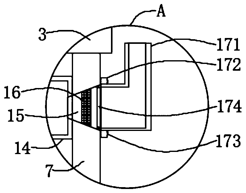
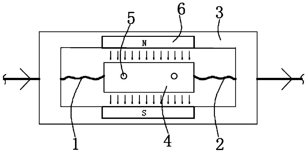
The invention discloses a heat dissipation device and method for AC small electrical components. The heat dissipation device includes a first wire and a second wire. A mounting block is arranged between the first wire and the second wire. A cavity is disposed in the mounting block. A conductive block is disposed in the cavity. The two ends of the conductive block are electrically connected to thefirst wire and the second wire, respectively. When the current flows in the forward direction, the conductive block is energized so as to move upward under the effect of a permanent magnet magnetic field, and squeeze an airbag through an adjustment rod, a plunger and a pressing block, so that the airbag exhales, and the exhalation of the airbag generates an air flow so as to complete the heat dissipation, wherein small electronic devices at specific locations can be targeted for heat dissipation by a guide mechanism. When the current flows in the backward direction, the conductive block movesdownward under the effect of the permanent magnet magnetic field so as to release the airbag through the adjustment rod, the plunger and the pressing block, so that the airbag inhales and prepare forthe next exhalation to ensure continuous use and continuous heat dissipation.

Description

Technical field [0001] The present invention relates to the technical field of heat dissipating devices, and in particular to a heat dissipating device for small electrical components of alternating current. Background technique [0002] At present, AC power is used in industrial electricity and even household electricity. When some electronic components are used, some heat will be generated, which will cause damage to some electronic components. Therefore, some electrical appliances need to install cooling fans to complete Heat dissipation, but in the actual use of the cooling fan, first of all, AC power cannot be used, and the AC power needs to be converted into DC power through a rectifier, so that it can be used, which will increase the cost; in addition, the cooling fan is large in size, so The packaging of electrical appliances becomes very large during installation, and the cooling fan cannot dissipate heat for some small specific electronic components, such as small chips...

Claims


Application Information

Patent Timeline
Patent Type & Authority Patents(China)
IPC IPC(8): H01L23/467
CPCH01L23/467
Inventor 向春兰
Owner 江苏森德邦信息科技有限公司
Learn More