Optical cable cross-connecting box with heat dissipation and cooling functions
An optical cable junction box and functional technology, applied in optics, light guides, optical components, etc., can solve the problems of single heat dissipation method, damaged components, poor heat dissipation efficiency and heat dissipation effect, etc., to improve dustproof effect, wide heat dissipation range, improve The effect of heat dissipation and heat dissipation efficiency
- Summary
- Abstract
- Description
- Claims
- Application Information
AI Technical Summary
Problems solved by technology
Method used
Image
Examples
Embodiment 1
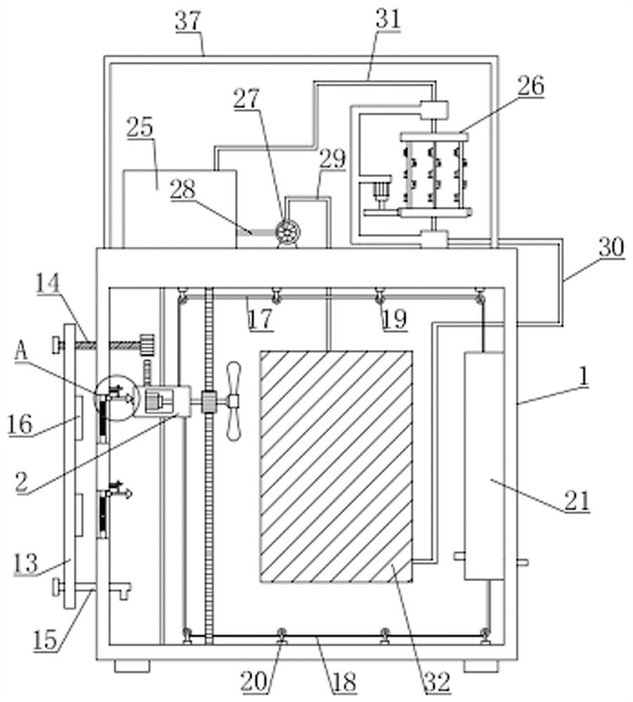
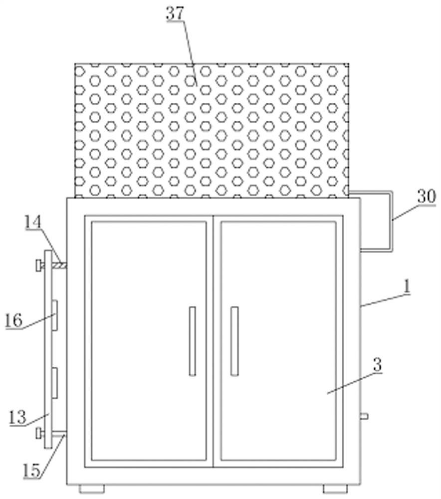
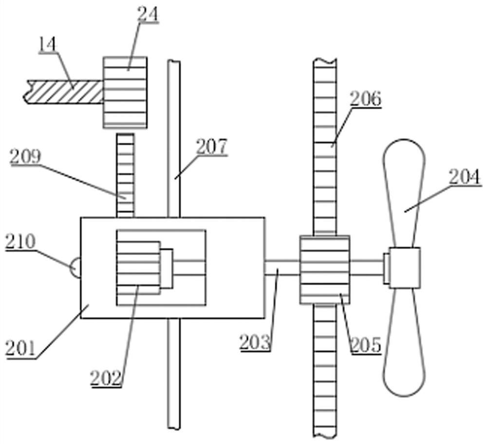
[0040] like Figure 1-8 As shown, the present invention proposes a cable splicing box with heat dissipation and cooling function, comprising a cable splicing box body 1, a door 3 and an air vent 4, the front of the cable splicing box body 1 is equipped with a box door 3 through a hinge, and the optical cable One side of the handover box body 1 is provided with multiple groups of vents 4, the vents 4 are used for ventilation and heat dissipation, the vents 4 are provided with a mounting plate 5, and the middle part of the mounting plate 5 is fixed with a dust filter 6, and the dust filter 6 is suitable for the incoming air. Dust filtering is carried out to improve the dust-proof effect, which helps to prevent the dust in the external air from causing damage to the internal components. The reciprocating air blowing assembly 2 is arranged in the optical cable transfer box body 1, and the reciprocating air blowing assembly 2 includes a movable box 201, a first motor 202, transmiss...
Embodiment 2
[0046] like Figure 10-11 As shown, the difference between this embodiment and Embodiment 1 is that the side of the movable box 201 facing away from the fan blade 204 is provided with an extruding protrusion 210, the extruding protrusion 210 is hemispherical, and the inner wall of the optical cable transfer box body 1 Multiple sets of first limit rods 11 are fixedly installed, and the first limit rods 11 correspond to the vents 4 one by one. The first limit rods 11 are slidably installed with extrusion plates 12, and the first limit rods 11 are far away from the optical cable handover. The bottom of one end of the inner wall of the box body 1 is fixedly provided with a connecting block for limiting, the extrusion plate 12 is connected with the inner wall of the optical cable transfer box body 1 through the first spring 10, and the bottom of the extrusion plate 12 is horizontally provided with an extrusion rod 7 to squeeze One end of the pressing bar 7 facing the air vent 4 is ...
Embodiment 3
[0048] like Figure 7 and Figure 9 As shown, the difference between this embodiment and Embodiment 1 and Embodiment 2 is that a second motor 2610 is fixedly installed in the middle of the C-shaped plate 2601 through a motor base, and the second motor 2610 is controlled by a control panel, which automatically controls the second motor. The opening and stopping of the motor 2610, the output shaft of the second motor 2610 is equipped with a third gear 2611, the second motor 2610 drives the output shaft, the output shaft drives the third gear 2611 to rotate, and the outer peripheral surface of the first hollow disc 2602 is fixedly installed with Ring gear 2612, the third gear 2611 is meshed with the ring gear 2612, when the third gear 2611 rotates, the ring gear 2612 rotates accordingly, the first connecting pipe 2607 is rotationally connected with the C-shaped plate 2601, the first connecting pipe 2607 It is fixedly connected with the first hollow disc 2602, the second connecti...
PUM
 Abstract
Description
Claims
Application Information
 - R&D
- Intellectual Property
- Life Sciences
- Materials
- Tech Scout
- Unparalleled Data Quality
- Higher Quality Content
- 60% Fewer Hallucinations
Browse by: Latest US Patents, China's latest patents, Technical Efficacy Thesaurus, Application Domain, Technology Topic, Popular Technical Reports.
© 2025 PatSnap. All rights reserved.Legal|Privacy policy|Modern Slavery Act Transparency Statement|Sitemap|About US| Contact US: help@patsnap.com


