Knee joint prosthesis

A knee joint prosthesis and component technology, applied in the field of knee joint prostheses, can solve problems such as easy damage of tibial pads, and achieve the effects of improving stability and reliability, prolonging service life, and increasing contact area

Pending Publication Date: 2018-12-07
上海博玛医疗科技有限公司
View PDF5 Cites 0 Cited by
  • Summary
  • Abstract
  • Description
  • Claims
  • Application Information

AI Technical Summary

Problems solved by technology

[0004] In order to solve the problem that the tibial liner is easily damaged due to the point impact of the femoral component on the limiting column in the prior art, the purpose of the present invention is to provide a knee joint prosthesis

Method used


Image

  • Knee joint prosthesis
  • Knee joint prosthesis
  • Knee joint prosthesis

Examples


Embodiment Construction

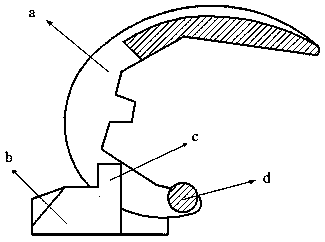
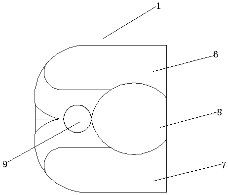
[0027] Such as image 3 The tibial liner 1 comprises the inner condyle movement track 6, the outer condyle movement track 7 and the spherical protrusion movement track 8 between the inner condyle movement track 6 and the outer condyle movement track 7, the end of the spherical protrusion movement track 8 is arranged There is a limiting component 9 tangent to the spherical protrusion moving track 8 , and the limiting component 9 is located on the tibial pad 1 .

[0028] Such as Figure 4 , the position of the spherical protrusion moving track 8 is lower than the inner condyle moving track 6 and the outer condyle moving track 7 .

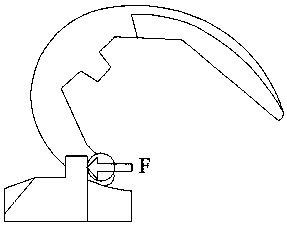
[0029] Such as Figure 5 , 6 , the femoral component 2 includes the medial condyle 3 and the lateral condyle 4, a spherical protrusion 5 is arranged between the medial condyle 3 and the lateral condyle 4, the medial condyle 3, the lateral condyle 4 and the spherical protrusion 5 form a cavity, and the spherical protrusion The stem 5 is located at ...


PUM


Abstract

The invention discloses a knee joint prosthesis. The knee joint prosthesis comprises a femur part anchored on a femur, a tibia part anchored on the femur part and a tibia liner located between the femur part and the tibia part. The femur part comprises an inner condyle and an outer condyle. A spherical projection is arranged between the inner condyle and the outer condyle. The tibia liner comprises an inner condyle motion track, an outer condyle motion track and a spherical projection motion track located between the inner condyle motion track and the outer condyle motion track. The end part of the spherical projection motion track is equipped with a limiting part tangent to the spherical projection motion track. The limiting part is located on the tibia liner. When the knee joint prosthesis performs high flexing motion, the contact area between the femur part and the tibia liner is increased. The motion impact of the femur part and the tibia liner is reduced. Smoothness and reliability of motion of the knee joint prosthesis are enhanced so that service lifetime of the knee joint prosthesis is prolonged.

Description

technical field [0001] The invention relates to the technical field of medical equipment, in particular to a knee joint prosthesis. Background technique [0002] Schematic diagram of the current knee prosthesis figure 1 As shown, it includes the tibial pad b and the femoral component a that slides freely on the tibial pad b, the end of one side of the femoral component a is provided with a spherical condyle d, and the tibial pad b is provided with a limiting column c , used to define the maximum sliding position of the femoral component a. [0003] When the femoral component a of the knee joint prosthesis rotates clockwise, the spherical condyle d rotates accordingly. During the rotation, the spherical condyle d does not contact the tibial pad b. When the spherical condyle d moves to the position of the limit column c, The spherical condyle d collides violently with the limiting column c, and the limiting column c prevents the spherical condyle d from continuing to rotate....

Claims


Application Information

Patent Timeline
Patent Type & Authority Applications(China)
IPC IPC(8): A61F2/38
CPCA61F2/38A61F2/3859A61F2/3877A61F2/30721A61F2002/2825A61F2002/2892
Inventor 尚亚光杨长桂唐飞
Owner 上海博玛医疗科技有限公司
Why Eureka
Try Eureka