Auxiliary supporting frame for ophthalmology department doctor operation

A technology used by ophthalmologists and surgery. It is applied in the field of auxiliary support frame for ophthalmologist surgery. It can solve the problems of poor breathing of patients, long operation time, and unfavorable success of surgery, so as to avoid the impact of operation results, avoid shortness of breath, good fixed effect

Active Publication Date: 2018-12-07
THE THIRD AFFILIATED HOSPITAL OF XINXIANG MEDICAL UNIV
12 Cites 9 Cited by

AI-Extracted Technical Summary

Problems solved by technology

When performing ophthalmic surgery on a patient, if the patient is seriously ill, the operation time is long, and the surgeon’s arm is in the air for a long time, so he is prone to fatigue. Excessive fatigue will affect the accuracy of the operation, which is not conducive to the success of the operation, and it is also due to the patient’s head The head often swings from side to side, which is not conducive to surgical...

Method used

During concrete use, at first pull down fixed bar 3, return spring is compressed, then this auxiliary support frame is placed on operating bed, then let go, return spring returns automatically, and L-shaped support is fixed with operating bed, Then let the patient lie on the operating bed, and use the head fixing belt 6, the fixing clip 7, the chin fixing belt 8 and the neck support pad 10 to fix the patient's head, and make the patient in a comfortable state, then put the face The bracket 9 covers the patient's face, and the sterile towel is placed on the face bracket to reduce the discomfort of the patient; finally, the distance between the two third telescopic rods 11 and the universal direction are adjusted according to the arm width of the ophthalmologist performing the operation. The angle of the adjuster 15 is properly adjusted, and the ophthalmologist can perform eye surgery.
The middle part of base plate 1 is provided with the first telescoping link 4, and the top of the first telescoping link 4 is connected with head fixture, and head fixture includes head fixture groove 5, head fixture belt 6, clamp 7 , chin fixing belt 8, face support 9 and neck support pad 10, the head fixing groove 5 is a cuboid structure and...

Abstract

The invention discloses an auxiliary supporting frame for ophthalmology department doctor operation. The supporting frame comprises a base plate, a head fixing device and an arm supporting device; thehead fixing device and the arm supporting device are arranged on the base plate; L-shaped supports with fixing rods are arranged on the two sides of the base plate, a first stretchable rod is arranged in the base plate, the top of the first stretchable rod is rotationally connected with the head fixing device comprising a head fixing groove, a head fixing belt, a fixing clamp, a chin fixing beltand a face support and a neck supporting pad; the base plate is further provided with a first sliding way extending from the center of the base plate to the end, a third stretchable rod is in slidingconnection with the first sliding way, and the arm supporting device is rotationally connected to the third stretchable rod. The supporting frame is simple in structure and convenient to use, the patient head fixing effect is good, the discomfort caused by directly covering the face of the patient with a sterile towel can be relieved, supporting is provided for the arms of an ophthalmology doctor,the influence on the operation caused by external factors such as arm aches of the doctor in the long-term operation process is avoided, and the auxiliary effect is good.

Application Domain

Operating tables

Technology Topic

EngineeringOphthalmology department +2

Image

  • Auxiliary supporting frame for ophthalmology department doctor operation
  • Auxiliary supporting frame for ophthalmology department doctor operation
  • Auxiliary supporting frame for ophthalmology department doctor operation

Examples

  • Experimental program(1)

Example Embodiment

[0023] The following are specific embodiments of the present invention combined with the accompanying drawings to further describe the technical solutions of the present invention, but the present invention is not limited to these embodiments.
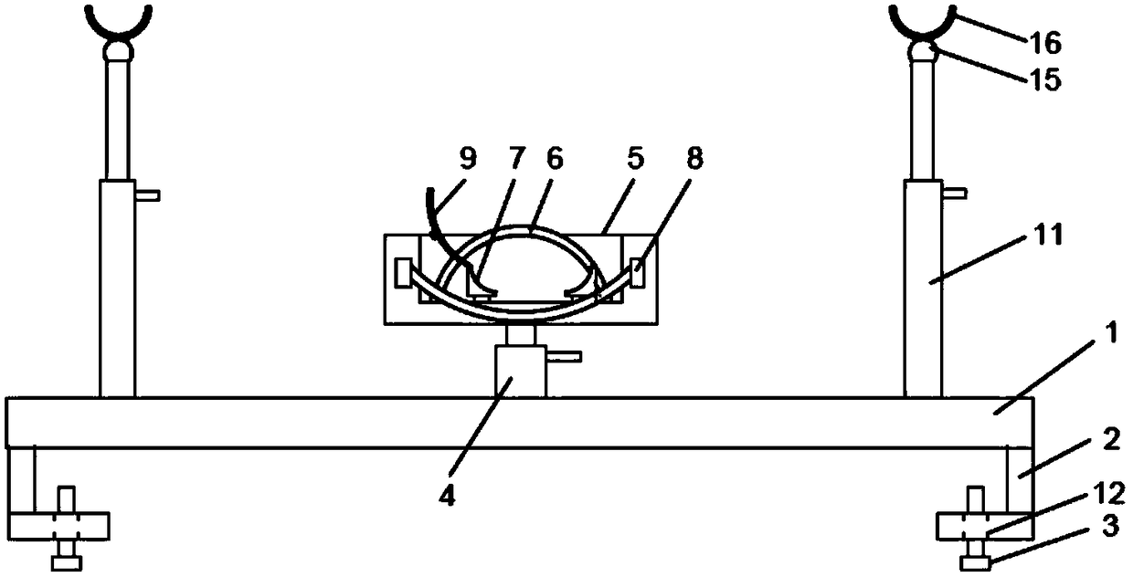
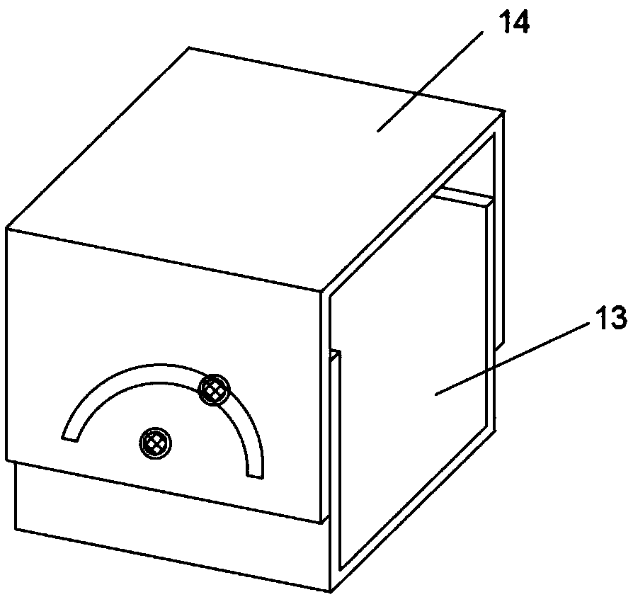
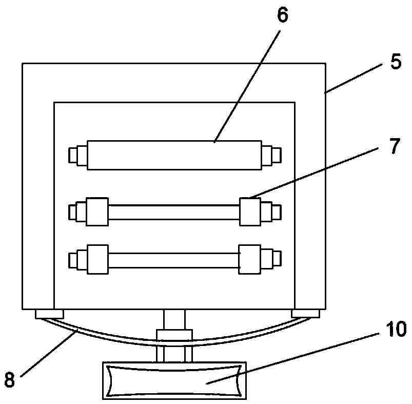
[0024] Such as Figure 1-Figure 3 As shown, an auxiliary support frame for an ophthalmologist's operation includes a bottom plate 1, a head fixing device, and an arm support device. The bottom plate 1 is used to connect the auxiliary support frame and the operating table, and the head fixing device is used to fix the head of the surgical patient. The arm support device is used to support the ophthalmologist’s arm to avoid the impact of the patient’s head shaking on the operation result.
[0025] A head fixing device is rotatably connected to the middle of the bottom plate 1, and arm support devices are slidably provided on both sides of the head fixing device on the bottom plate 1;
[0026] L-shaped brackets 2 are provided on both bottoms of the bottom plate 1, and fixed rods 3 are provided on the L-shaped bracket 2, and the L-shaped brackets 2 and the fixed rods 3 are used to fix the auxiliary support frame;
[0027] The middle of the bottom plate 1 is provided with a first telescopic rod 4, and the top of the first telescopic rod 4 is rotatably connected with a head fixing device. The head fixing device includes a head fixing groove 5, a head fixing band 6, a fixing clip 7, and a chin fixing device. Belt 8, face support 9 and neck support cushion 10. The head fixing groove 5 is a rectangular parallelepiped structure and the upper half is provided with a square groove communicating with the front side, and the inner rear side of the square groove is slidingly provided with a head fixing With 6, multiple sets of fixing clips 7 are slidably arranged on the middle side of the square groove, and the fixing clips 7 on the same side of the square groove are hinged to a face support 9, that is, multiple fixing clips on the left side of the square groove The clip is hinged with a face support 9 or a plurality of fixing clips located on the right side of the square groove are hinged with a face support 9. The two sides of the front side of the head fixing groove 5 are detachably provided with a chin fixing strap 8. The front side of the part fixing groove 5 is also provided with a neck support pad 10, the head fixing band 6 is used to fix the forehead, the multiple sets of fixing clips 7 are used to fix the head, the chin fixing band 8 is used to fix the chin, and the face support frame 9 is used to place a sterile towel to reduce the discomfort caused by placing the sterile towel directly on the patient's face. The neck support pad 10 is used to support the patient's neck.
[0028] Preferably, the L-shaped bracket includes a first horizontal plate and a first vertical plate. The first horizontal plate is provided with a first through hole 12, the first through hole 12 is provided with a fixing rod 3, and the inner wall of the first through hole 12 is fixed The outer wall of the rod 3 is smooth. The two ends of the fixed rod 3 are respectively provided with upper limit blocks and lower limit blocks. The part of the fixed rod 3 between the first horizontal plate and the upper limit block is provided with a return spring, which is fixed by pulling down The rod 3 compresses the return spring, and then places the auxiliary support frame on the operating bed, then releases the hand, the return spring automatically returns, and fixes the L-shaped bracket to the operating bed.
[0029] Preferably, the front side of the head fixing groove 5 is provided with a second telescopic rod below the square groove, the end of the second telescopic rod is provided with a first support plate, and the first support plate is detachably provided with a neck Support pad 10.
[0030] Preferably, the first telescopic rod 4 is a hydraulic telescopic structure and is provided with a control board for controlling the expansion and contraction of the first telescopic rod 4, the top of the first telescopic rod 4 is fixedly connected with a first connecting member 13, and the first connecting member 13 rotates upward. Connected with a second connecting piece 14;
[0031] The first connecting member 13 is a U-shaped structure including two second vertical plates and a second horizontal plate. Both second vertical plates are provided with two parallel second through holes. The second connecting member 14 includes An n-shaped structure of two third vertical plates and a third horizontal plate. The positions corresponding to the two second through holes on the two third vertical plates are respectively provided with a third through hole and an arc-shaped slot, and the arc-shaped slot is located Above the third through hole, the first connecting member 13 and the second connecting member 14 pass through the first screw passing through the third through hole and the second through hole located above, and the first screw passing through the arc groove and the second through hole located below. The second screw of the two through holes is rotationally connected, and the third horizontal plate is fixedly connected to the head fixing groove 5.
[0032] Preferably, the bottom plate 1 is provided on both sides of the first telescopic rod 4 with a first slideway extending from the center of the bottom plate 1 to the end, and a third telescopic rod 11 is slidably connected to the two first slideways. The top of the third telescopic rod 11 is rotatably connected with an arm support device;
[0033] The arm support device includes a universal adjuster 15 connected to the third telescopic rod 11 and a second support plate 16 connected to the universal adjuster 15. The second support plate 16 is connected with a soft pad, and the soft pad is detachably provided with Waterproof protective cover.
[0034] Preferably, a second slideway and a plurality of third slideways are arranged in parallel in the direction groove, two second slideways are provided on the second slideway, and two third slideways are provided on each third slideway. , The two ends of the head fixing strap 6 are respectively detachably arranged on two second sliding blocks located on the same second slideway, and each third sliding block is detachably provided with a fixing clip 7, a fixing clip 7 It is a right-angled triangular prism, and the slope of the right-angled triangular prism is concave. The face support 9 is an arc-shaped panel, and there are multiple vents on both sides. One side of the face support 9 is on the same side of the square groove. Two fixing clips 7 are hinged, and the other side of the face support 9 is detachably connected to the plurality of fixing clips 7 on the other side of the square groove.
[0035] Preferably, the head fixing band 6 and the chin fixing band 8 are both elastic bandages, and the length can be adjusted, the square groove, the head fixing band 6, the face fixing clip 7, the face fixing clip 9 and the chin fixing belt 8 A soft pad with a waterproof protective cover is detachable inside.
[0036] In specific use, first pull the fixing rod 3 downward to compress the return spring, then place the auxiliary support frame on the operating bed, then let go, the return spring automatically recovers, and fix the L-shaped bracket with the operating bed, and then let the patient Lie on the operating table, and use the head fixation band 6, the fixation clip 7, the chin fixation band 8 and the neck support cushion 10 to fix the patient's head and keep the patient in a comfortable state, and then cover the face support 9 Facing the patient’s face, place a sterile towel on the face support to alleviate the patient’s discomfort; finally adjust the distance between the two third telescopic rods 11 and the universal adjuster 15 according to the arm width of the ophthalmologist in the operation. After adjusting the angle, the ophthalmologist can perform eye surgery.
[0037] The above are only the preferred embodiments of the present invention. It should be pointed out that for those of ordinary skill in the art, without departing from the principle of the present invention, several improvements and modifications can be made, and these improvements and modifications should also be made. It is regarded as the protection scope of the present invention.

PUM

no PUM

Description & Claims & Application Information

We can also present the details of the Description, Claims and Application information to help users get a comprehensive understanding of the technical details of the patent, such as background art, summary of invention, brief description of drawings, description of embodiments, and other original content. On the other hand, users can also determine the specific scope of protection of the technology through the list of claims; as well as understand the changes in the life cycle of the technology with the presentation of the patent timeline. Login to view more.

Similar technology patents

Hemodialysis upper limb fixing device

Owner:CHENGDU KECHUANG JIASI TECH

A single-port laparoscopic instrument system for V-NOTES surgery

Owner:SHANGHAI FIRST MATERNITY & INFANT HOSPITAL

Classification and recommendation of technical efficacy words

  • Good fixed effect

Drawing board for environmental art design

InactiveCN109484063AGood fixed effectImprove drawing efficiency
Owner:安陆风常建筑景观规划设计有限公司

Gearbox device of speed regulating tapping machine

InactiveCN109926619AAvoid uneven forceGood fixed effect
Owner:安徽同发设备股份有限公司
Why Eureka
Try Eureka