Idler wheel limiting device

The technology of a limit device and roller, which is applied in the limit field of rollers, can solve problems such as troublesome operation and poor fixing effect, and achieve the effects of cost saving, good fixing effect and convenient operation

Inactive Publication Date: 2019-02-05
饶皇
View PDF0 Cites 3 Cited by
  • Summary
  • Abstract
  • Description
  • Claims
  • Application Information

AI Technical Summary

Problems solved by technology

[0003] The purpose of the present invention is to overcome the defects and problems of troublesome operation and poor

Method used


Image

  • Idler wheel limiting device
  • Idler wheel limiting device
  • Idler wheel limiting device

Examples


Embodiment Construction

[0020] The present invention will be described in further detail below in conjunction with the accompanying drawings and specific embodiments

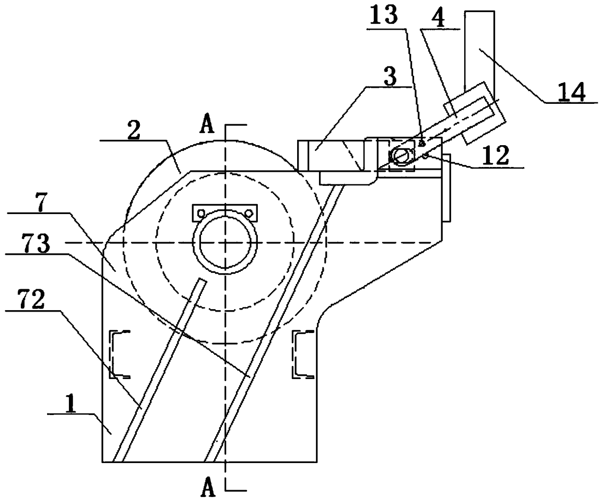
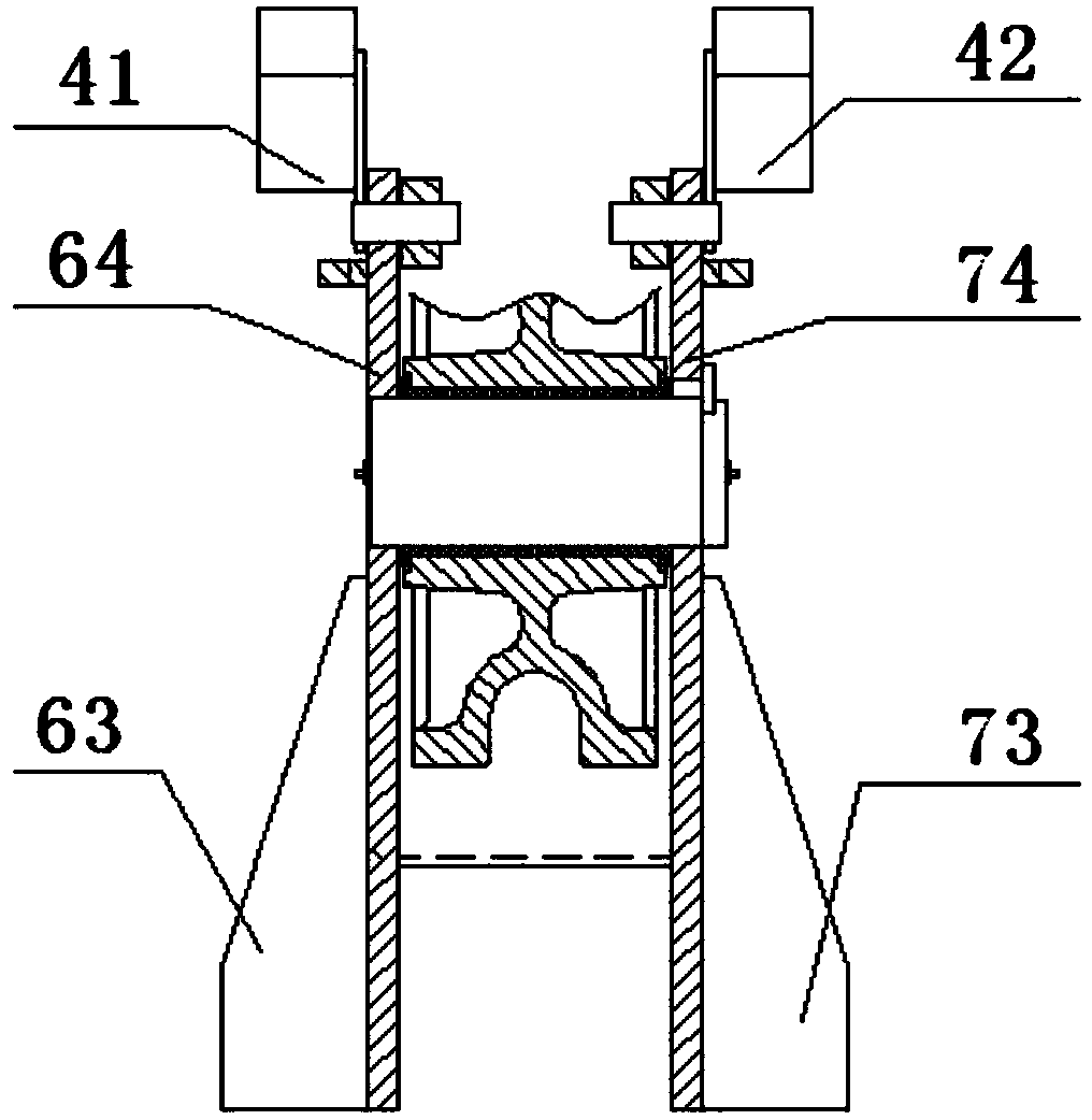
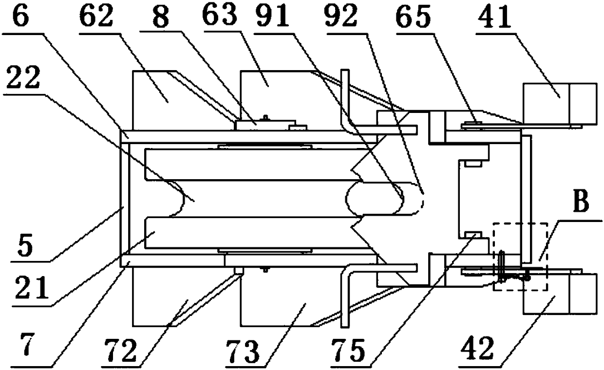
[0021] see figure 1 — Figure 4 , a roller limiting device, including a machine base 1, a roller 2, a chain stop mechanism 3, a balance mechanism 4 and a handle 14, the bottom of the handle 14 is connected with the chain stop mechanism 3 through a balance mechanism 4, and the machine base 1 includes the front plate 5, the left side plate 6 and the right side plate 7, the left shaft hole 61 and the right shaft hole 71 are provided with a hole shaft 8, and the hole shaft 8 is covered with the above-mentioned roller 2;

[0022] The left side plate 6 is provided with a left front support wing 62 and a left rear support wing 63, and the right side plate 7 is provided with a right front support wing 72 and a right rear support wing 73, and the left front support wing 62 and the right front support wing 72 Symmetrical to each other, the lef...


PUM


Abstract

The invention discloses an idler wheel limiting device. The idler wheel limiting device comprises a device base, an idler wheel, a chain stopping mechanism, a balancing mechanism and a handle; the bottom of the handle is connected with the chain stopping mechanism through the balancing mechanism, hole shafts are arranged on a left side plate and a right side plate on the device base, and the idlerwheel sleeves the hole shafts; and the top protruding parts of the left side plate and the right side plate are fixedly connected with the left and right sides of the chain stopping mechanism and a left handle and a right handle of the balancing mechanism, and a U-shaped opening knife switch is arranged at the center of the chain stopping mechanism. According to the idler wheel limiting device, chain stopping is easy, the fixing effect is good, the chain-out angle range is wide, and operation is convenient.

Description

technical field [0001] The invention relates to a roller limiting device, which is particularly suitable for the limiting of rollers used for fixing anchor chains after a ship breaks down. Background technique [0002] The chain stopper is a machine that fixes the anchor chain and bears the tension of the anchor chain after the ship breaks down. The roller limit device blocks the vertical chain of the anchor chain through the knife to realize the function of fixing the anchor chain. The traditional chain stopper is designed according to the CB / T3844-2000 standard. The vertical chain of the anchor chain is placed in the groove of the roller, and the horizontal chain is in contact with the outer circle of the roller. . However, when the existing chain stopper fixes the anchor chain, the stop mechanism and the pin fixing mechanism need to work together, which is cumbersome to operate and has a bad fixing effect. Contents of the invention [0003] The purpose of the present...

Claims


Application Information

Patent Timeline
IPC IPC(8): B63B21/18
CPCB63B21/18
Inventor 饶皇
Owner 饶皇
Why Eureka
Try Eureka