Equipment for fixing bars when being cut by saws

A fixed rod and sawing technology, which is applied in the field of mechanical processing, can solve the problems of potential safety hazards and affecting processing efficiency, and achieve the effects of improving clamping stability, safety, and service life

Inactive Publication Date: 2013-09-11
四川东方能源科技股份有限公司
View PDF6 Cites 3 Cited by
  • Summary
  • Abstract
  • Description
  • Claims
  • Application Information

AI Technical Summary

Problems solved by technology

When sawing, the material to be sawed will be subjected to vertical downward pressure from the saw blade and cutting force in the horizontal direction. The cutting force in the horizontal direction will cause the material to be sa

Method used


Image

  • Equipment for fixing bars when being cut by saws
  • Equipment for fixing bars when being cut by saws
  • Equipment for fixing bars when being cut by saws

Examples


Example Embodiment

[0029] Example 1:

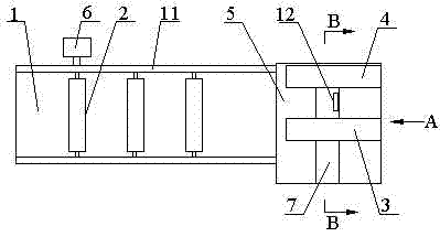
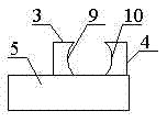
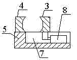
[0030] Such as Figure 1~Figure 3 As shown, the equipment used to fix the bar during sawing includes a working table 1, a rotating shaft 2, a movable clamping block 3, a fixed clamping block 4, a clamping table 5, and a motor 6. A plurality of rotating shafts 2 are rotatably arranged on On the worktable 1, the output end of the motor 6 is connected with the rotating shaft 2. The clamping table 5 is set at the front end of the worktable 1, the clamping table 5 is provided with a chute 7, and the fixed clamping block 4 is fixed on the clamping table 5. On one side, the movable clamping block 3 is arranged opposite to the fixed clamping block 4. The bottom of the movable clamping block 3 is slidably arranged in the chute 7; it also includes a hydraulic cylinder 8 fixed in the chute 7, and the hydraulic cylinder 8 is telescopic The end is connected with the bottom of the movable clamping block 3.

[0031] When working, the motor 6 drives the shaft 2 to rotate, and...


PUM


Abstract

The invention discloses equipment for fixing bars when being cut by saws. The equipment comprises a workbench, rotary shafts, a movable clamping block, a fixing clamping block, a clamping table and a motor. The rotary shafts are rotationally arranged on the workbench, an output end of the motor is connected with the rotary shafts, the clamping table is arranged at the front end of the workbench, a spout is formed on the clamping table, the fixing clamping block is fixed on one side of the clamping table, the movable clamping block is arranged opposite to the fixing clamping block, and the bottom of the movable clamping block is arranged in the spout in a sliding manner; the equipment further comprises a hydraulic cylinder fixed in the spout, and a telescopic end of the hydraulic cylinder is connected with the bottom of the movable clamping block. The equipment for fixing the bars when being cut by saws has the advantages that the equipment can fix the bars well and prevent the bars from moving under cutting force.

Description

technical field [0001] The invention relates to the field of mechanical processing, in particular to a device for fixing a bar when sawing. Background technique [0002] In the field of machining, sawing operations are often involved. When sawing, the material to be sawed will be subjected to vertical downward pressure from the saw blade and cutting force in the horizontal direction. The cutting force in the horizontal direction will cause the material to be sawed to be displaced in the horizontal direction, which not only affects Processing efficiency, and there are potential safety hazards. [0003] Currently, during sawing operations, there is no device that can well fix the material to be sawed. Contents of the invention [0004] The purpose of the present invention is to overcome the deficiencies of the prior art and provide a device for fixing a bar during sawing that can well fix the material to be sawed. [0005] The object of the present invention is achieved t...

Claims


Application Information

Patent Timeline
IPC IPC(8): B23Q3/08B23Q7/05
Inventor 王曾勇叶礼
Owner 四川东方能源科技股份有限公司
Why Eureka
Try Eureka