Soil environment sampling and monitoring device with portable energy

A monitoring device and soil technology, applied in sampling devices, soil material testing, material inspection products, etc., can solve the problems of troublesome work, influence of monitoring results, poor cleaning effect of sampling tools, etc., so as to reduce resistance and improve accuracy. Effect

Active Publication Date: 2020-04-17
XIJING UNIV
View PDF19 Cites 3 Cited by
  • Summary
  • Abstract
  • Description
  • Claims
  • Application Information

AI Technical Summary

Problems solved by technology

[0002] Soil monitoring is to use appropriate measurement methods to measure various physical and chemical properties of soil, such as iron, manganese, total potassium, organic matter, total nitrogen, available phosphorus, total phosphorus, moisture, total arsenic, available boron, fluoride, chloride, mineral oil and total salinity, etc. Soil sampling monitoring equipment needs to sample the soil first and then monitor. However, the existing soil sampling is that people use sampling tools to manually shovel the soil for sampling, and it is impossible to accurately obtain the depth of the soil. Therefore, it may It will affect the monitoring results. At the same time, the sampling tool needs to be cleaned after the sampling is completed, so as to avoid the residual soil on the sampling tool from being mixed into the next sampling soil. However, it is inconvenient to carry more cleaning equipment when sampling outdoors, so The cleaning effect of the sampling tool is not good, and when sampling outdoors in rainy and snowy weather, in order to avoid the interference of the monitoring device from rain and snow, people need to set up tents to protect the monitoring device, which brings troubles to people's work

Method used


Image

  • Soil environment sampling and monitoring device with portable energy
  • Soil environment sampling and monitoring device with portable energy
  • Soil environment sampling and monitoring device with portable energy

Examples


Embodiment Construction

[0024] The technical solutions of the present invention will be clearly and completely described below in conjunction with the embodiments and accompanying drawings. Apparently, the described embodiments are only some of the embodiments of the present invention, not all of them. Based on the embodiments of the present invention, all other embodiments obtained by persons of ordinary skill in the art without creative efforts fall within the protection scope of the present invention.

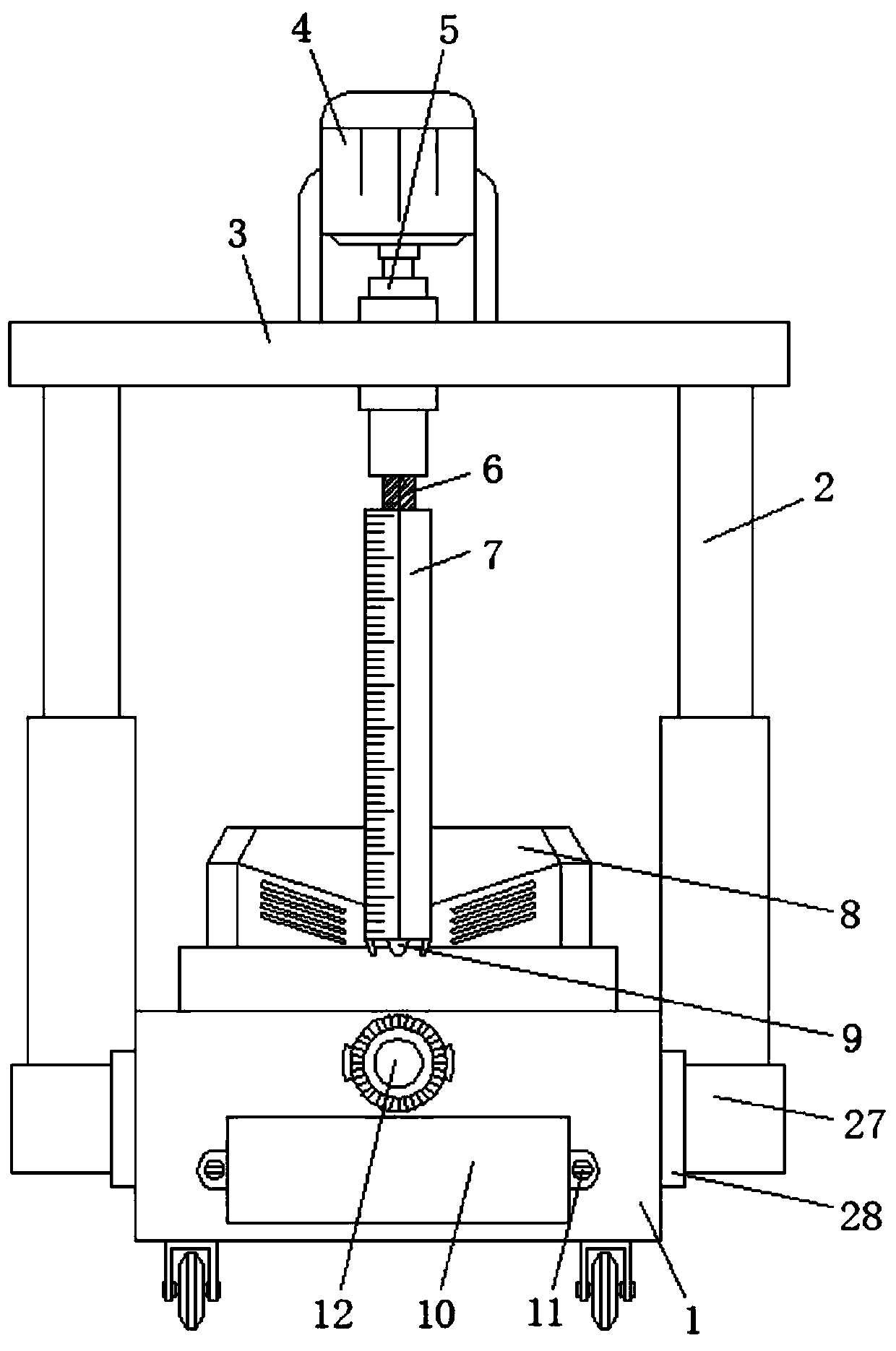
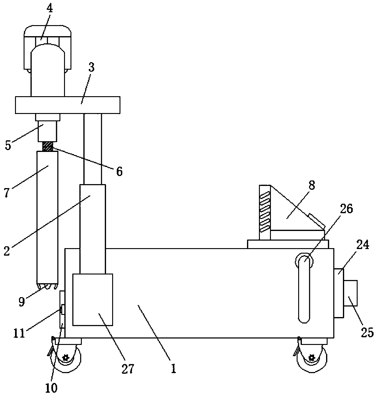
[0025] refer to figure 1 and figure 2 , a soil environment sampling and monitoring device with portable energy, comprising a bottom case 1, an electric push rod 2 is rotatably connected to the left and right sides of the bottom case 1, the top of the electric push rod 2 is fixedly connected to the lower surface of the top plate 3, and the top plate 3 is clamped with a first bearing, and the first bearing is sleeved with a first rotating shaft 5, the top of the first rotating shaft 5 is fixedly co...


PUM


Abstract

The invention discloses a soil environment sampling and monitoring device with portable energy, which comprises a bottom shell. Electric push rods are rotationally connected to the left and right sidesurfaces of the bottom shell; the top end of the electric push rod is connected with a top plate, a first bearing is clamped to the top plate, a first rotating shaft is sleeved with the first bearing, the top end of the first rotating shaft is fixedly connected with an output shaft of the motor, two half-threaded pipes are threaded at the bottom end of the first rotating shaft, and half-samplingpipes are fixedly connected to the lower surfaces of the half-threaded pipes; a treatment groove is formed in the upper surface of the bottom shell, a partition plate is arranged in the treatment groove, a water spray nozzle and a stirring blade are arranged on one side of the partition plate, and an electric heating pipe and a baffle are arranged in the other side of the partition plate; a placement groove is formed in the front face of the bottom shell, a water tank is arranged in the bottom shell, and the water pump in the water tank is communicated with the water spray nozzle; and the motor drives the half-sampling pipe to drill into the ground, soil with accurate depth can be obtained, and the sampling tool is simple to clean and convenient to use.

Description

technical field [0001] The invention belongs to the technical field of soil sampling and monitoring, in particular to a soil environment sampling and monitoring device with portable energy. Background technique [0002] Soil monitoring is to use appropriate measurement methods to measure various physical and chemical properties of soil, such as iron, manganese, total potassium, organic matter, total nitrogen, available phosphorus, total phosphorus, moisture, total arsenic, available boron, fluoride, chloride, mineral oil and total salinity, etc. Soil sampling monitoring equipment needs to sample the soil first and then monitor. However, the existing soil sampling is that people use sampling tools to manually shovel the soil for sampling, and it is impossible to accurately obtain the depth of the soil. Therefore, it may It will affect the monitoring results. At the same time, the sampling tool needs to be cleaned after sampling to prevent the residual soil on the sampling too...

Claims


Application Information

Patent Timeline
Patent Type & Authority Applications(China)
IPC IPC(8): G01N1/08G01N33/24
CPCG01N1/08G01N33/24
Inventor 渠杭州王引卫王丙铮吴平平
Owner XIJING UNIV
Why Eureka
Try Eureka