Walking stick special for the blind

A cane for the blind and blind hole technology, which is applied in the direction of equipment to help people walk, physical therapy, etc., can solve the problems of strenuous walking, easy fatigue of the hands, and slow down walking speed, so as to save energy, facilitate perception, operation, and use convenient effect

Inactive Publication Date: 2018-12-07
CHANGZHOU COLLEGE OF INFORMATION TECH
View PDF0 Cites 1 Cited by
  • Summary
  • Abstract
  • Description
  • Claims
  • Application Information

AI Technical Summary

Problems solved by technology

[0003] When a blind person walks on the blind road, he uses the traditional guide stick to touch forward, left and right while walking, and is not sensitive to the touch of the stripes and corrugations on the blind bricks, so the walking speed is slowed down, and even easy to go astray
[0004] In addition, when the blind person walks, he still needs to hold the guide stick, so the hand needs to be lifted all the time, and walking is more difficult; Blind stick, hand fatigue easily

Method used


Image

  • Walking stick special for the blind
  • Walking stick special for the blind
  • Walking stick special for the blind

Examples


Embodiment 1

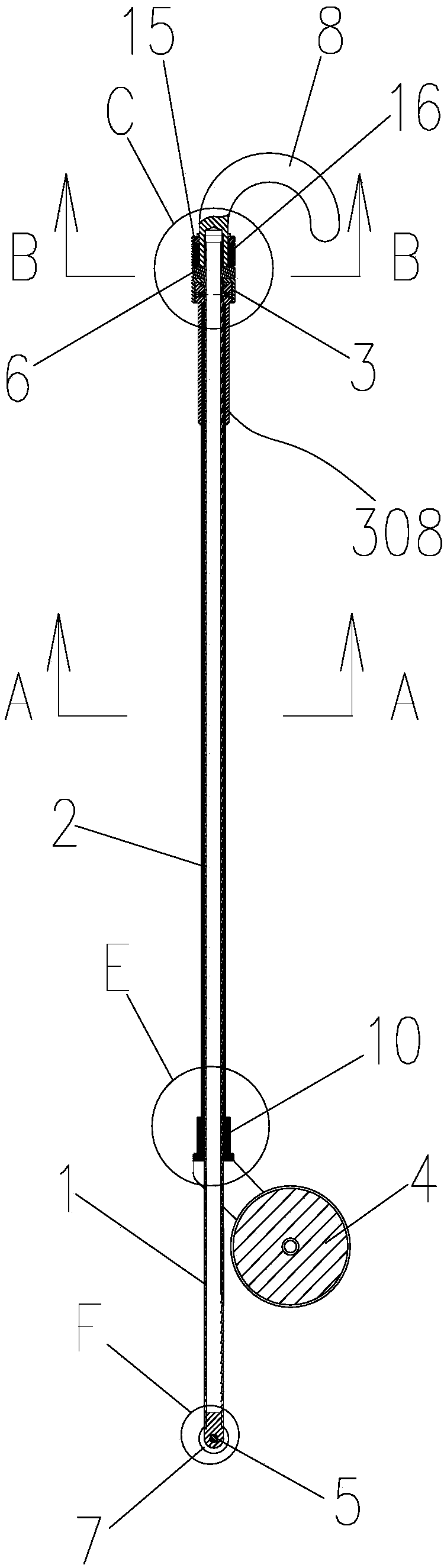
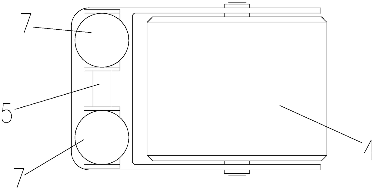
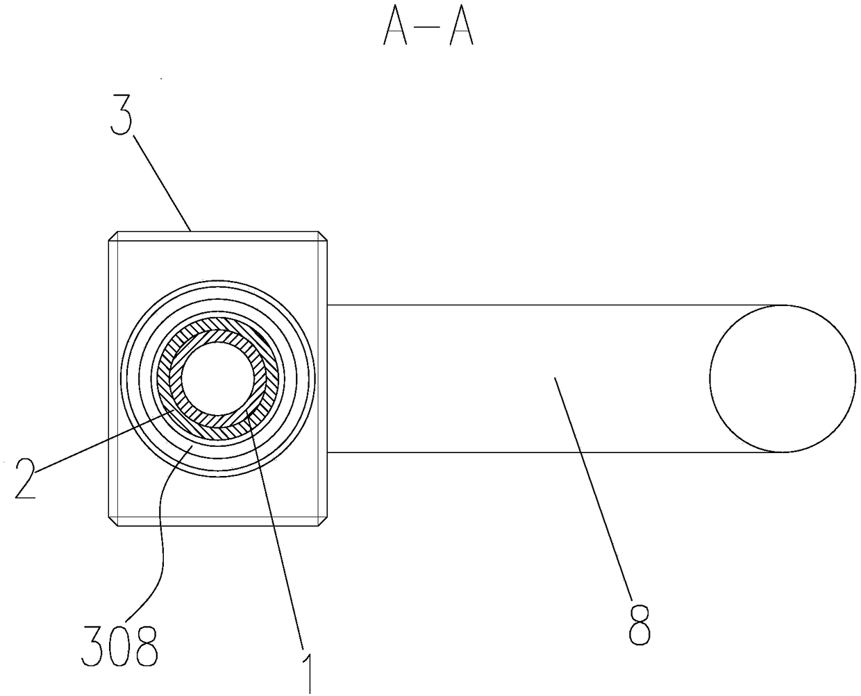
[0059] Such as Figure 1-Figure 10 The shown embodiment one of a kind of special walking stick of the present invention includes an inner rod 1 and an outer tube 2, the top of the outer tube 2 is vertically fixed with a first rectangular block 3, and the bottom end of the outer tube 2 is installed with a The upper roller 4, the rolling surface of the upper roller 4 faces the side of the outer tube 2; the inner rod 1 is rotatably connected to the outer tube 2, and the bottom end of the inner rod 1 protruding outside the outer tube 2 is vertically fixed with a cross bar 5, and the inner rod 1 The top of 1 penetrates to the outside of the first rectangular block 3, the top of the inner rod 1 is vertically fixed with a second rectangular block 6, the center of the first rectangular block 3, the center of the second rectangular block 6 and the central axis of the inner rod 1 coincide The shape of the contacting rectangular surfaces of the first rectangular block 3 and the second re...

Embodiment 2

[0077]This embodiment differs from Embodiment 1 in that: when it is in use, the wide groove height of the T-shaped slot 13 of this embodiment is greater than the rod diameter of the cross bar 5, and at the same time, the inclined cross bar 5 can be placed in a T-shaped Rotate in the wide slot of the slot 13, preferably, the height of the wide slot of the T-shaped slot 13 is equal to the bar length of the cross bar 5, except that, other structures are the same as the first embodiment. Adaptively, the notch width of the T-shaped slot 13 should be greater than the diameter of the crossbar 5 and the diameter of the outer tube 2, so as to facilitate placing the T-shaped structure formed by the crossbar 5 and the inner rod 1 into the notch. When it is necessary to put the T-shaped structure into and fit in the T-shaped groove 13, the upper roller 4 is supported on the blind guideway as a lever, and the top of the inner rod 1 is pressed down to a certain height, so that the T-shaped s...

Embodiment 3

[0080] The difference between this embodiment and the first embodiment is that the T-shaped slot 13 can be replaced by an L-shaped slot, and other structures are the same as the first embodiment. Correspondingly, the cross bar 5 and the inner bar 1 form an L-shaped structure, and can fit to slide in the L-shaped groove, and the corresponding operations and effects are the same as those in the first embodiment.


PUM


Abstract

The invention belongs to the field of assisting aids for physically-challenged people, and particularly relates to a walking stick special for the blind. The walking stick comprises an inner rod and an outer pipe. A first rectangular block is vertically fixed to the top end of the outer pipe. An upper wheel is installed at the bottom end of the outer pipe. The inner rod is rotationally connected into the outer pipe. A transverse rod is vertically fixed to the bottom end, extending out of the outer pipe, of the inner rod. The top end of the inner rod penetrates out of the first rectangular bock. A second rectangular block is vertically fixed to the top end of the inner rod. The axes of the center of the first rectangular block, the center of the second rectangular block and the center of the inner rod coincide. The contact rectangular faces of the first rectangular block and the second rectangular block are the same in shape. The walking stick has the advantages that guiding can be conducted through a T-type groove when a user walks straight or turns around, the matched walking stick feeds back the sense of touch for guiding walking, the sense of touch is sensitive, the walking speed is increased, and the user can hardly go off course; when the blind walks, the walking stick can be pushed to move on a guiding sidewalk only by slightly exerting thrust instead of lifting force, and the user walks easily, can push the walking stick by a single hand conveniently and can hardly feel tired.

Description

technical field [0001] The invention belongs to the field of auxiliary appliances for the disabled, and in particular relates to a walking stick for the blind. Background technique [0002] Usually the traditional blind guide stick used by the blind is a straight rod-shaped blind stick, and the road surface information is obtained by touching the ground while walking. [0003] When a blind person walks on the blind road, he uses the traditional guide stick to touch forward, left and right while walking, and is not sensitive to the touch of the stripes and corrugations on the blind bricks, so the walking speed is slowed down, and even Easy to go astray. [0004] In addition, when the blind person walks, he still needs to hold the guide stick, so the hand needs to be lifted all the time, and walking is more difficult; With a blind stick, the hands are easily fatigued. Contents of the invention [0005] The purpose of the present invention is to overcome the defects existi...

Claims


Application Information

Patent Timeline
Patent Type & Authority Applications(China)
IPC IPC(8): A61H3/06
CPCA61H3/066A61H3/061A61H3/068A61H2003/063
Inventor 周彩根刘锁娣
Owner CHANGZHOU COLLEGE OF INFORMATION TECH
Why Eureka
Try Eureka