
LED support three dimensional ink coating die

A three-dimensional, mold-based technology, which is applied to the device and coating of the surface coating liquid, can solve the problem of not being able to brush black lamp beads, and achieve the effect of accurate parking position

Pending Publication Date: 2018-12-07
DONGGUAN CHANGTONG PRECISION HARDWARE
View PDF0 Cites 0 Cited by
  • Summary
  • Abstract
  • Description
  • Claims
  • Application Information

AI Technical Summary

Problems solved by technology

[0005] In order to solve the technical problem that only the upper surface of the LED lamp bead can be blackened, but not the surroundings of the lamp bead, the invention provides a three-dimensional ink brushing mold for LED brackets, which includes

Method used


Image

  • LED support three dimensional ink coating die
  • LED support three dimensional ink coating die
  • LED support three dimensional ink coating die

Examples


Embodiment 1

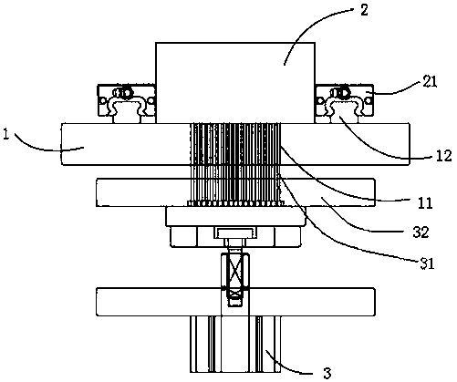
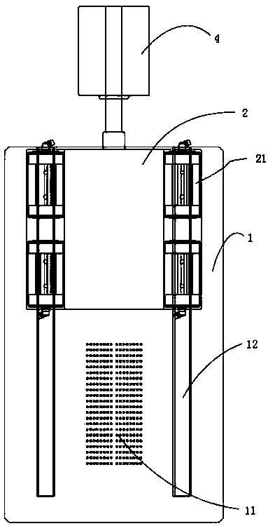
[0033] like figure 2 and Figure 4 , a LED bracket three-dimensional ink brush mold, which includes

[0034] A frame, the frame is provided with a bottom plate 1, and one side of the bottom plate 1 is provided with several through holes 11 penetrating the bottom plate from top to bottom;

[0035] The ink cartridge 2 is arranged above the other side of the bottom plate 1, the ink cartridge 2 is a box body with an open bottom, and the ink cartridge is arranged on the bottom plate 1 so as to be movable back and forth;

[0036] The core 31 is movably arranged in the through hole 11, and the core 31 fits with the through hole 11 with a small gap;

[0037] The first driving device 3 is connected to the lower end of the core 31 through a connecting plate, and the first driving device 3 is arranged on the frame and located below the bottom plate 1 .

[0038] The first driving device 3 is a pneumatic telescopic device, and the pneumatic telescopic device includes a telescopic rod a...

Embodiment 2

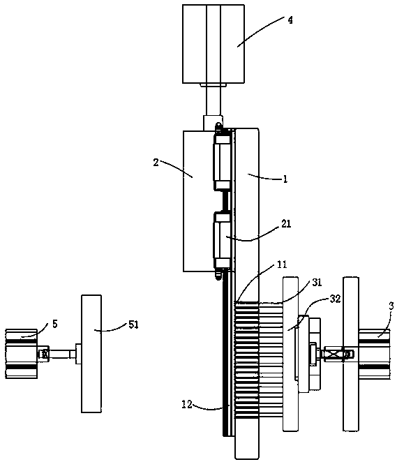
[0046] like image 3 , a LED bracket three-dimensional ink brush mold, which includes

[0047] A frame, the frame is provided with a bottom plate 1, and one side of the bottom plate 1 is provided with several through holes 11 penetrating the bottom plate from top to bottom;

[0048] The ink cartridge 2 is arranged above the other side of the bottom plate 1, the ink cartridge 2 is a box body with an open bottom, and the ink cartridge is arranged on the bottom plate 1 so as to be movable back and forth;

[0049] The core 31 is movably arranged in the through hole 11, and the core 31 fits with the through hole 11 with a small gap;

[0050] The first driving device 3 is connected to the lower end of the core 31 through a connecting plate, and the first driving device 3 is arranged on the frame and located below the bottom plate 1 .

[0051] The first driving device 3 is a pneumatic telescopic device, and the pneumatic telescopic device includes a telescopic rod and a cylinder, a...


PUM


Abstract

The invention discloses an LED support three dimensional ink coating die. The LED support three dimensional ink coating die comprises a machine frame, an ink box, cores, and a first driving device; the machine frame is provided with a bottom plate; one side of the bottom plate is provided with a plurality of through holes penetrating the bottom plate from top to bottom; each through hole comprisesa cavity terminal and a core hole terminal arranged in an up-down manner, and a step is arranged between the cavity terminal and the core hole terminal; the orthographic projection area of each corehole terminal is smaller than the orthographic projection area of the corresponding cavity terminal; each core hole terminal and the corresponding cavity terminal are designed to be clearance fit; theink box is arranged on the upper part of the other end of the bottom plate; the ink box is a box body with a bottom opening, is arranged on the bottom plate, and is capable of moving back and forth on the bottom plate; the cores are movably arranged in the through holes, and the cores and the through holes are designed to be clearance fit; the first driving device is connected with the lower endsof the cores through a connecting plate; the first driving device is arranged on the machine frame and below the bottom plate. When the LED support three dimensional ink coating die is used for LED lamp bead white glue ink coating, the upper surfaces and the four sides of LED lamp beads can be coated with ink, LED lamp bead resolution is increased without reduction of LED lamp bead reflector cupreflection effect.

Description

technical field [0001] The invention relates to a mold, in particular to a three-dimensional ink brushing mold for LED brackets. Background technique [0002] With the rise of the LED lighting industry, LED has been developed and applied. Because of its advantages of small size, high reliability, and low batch manufacturing cost, it soon became the main body of application in the market. [0003] Countries attach great importance to the LED industry, and LED lamp beads also show the following development directions: 1. Development from low power to high power; 2. Development from lighting to industrial applications; 3. Power consumption is getting lower and lower; 4. High power efficient production. [0004] LED bracket RGB products are widely used in LED display screens. In order to improve the resolution, the shape of the lamp bead must not be exposed. This requires the use of black glue or white glue to brush the ink. Although black glue can be used, the reflective cup o...

Claims


Application Information

Patent Timeline
IPC IPC(8): B05C3/109B05C11/11B05C11/00
CPCB05C3/109B05C11/00B05C11/11
Inventor 谢安全李杰赵申成
Owner DONGGUAN CHANGTONG PRECISION HARDWARE
Learn More