Reinforcing steel bar cut-off and feeding device

A technology of feeding device and steel bar is applied in the field of pipe pile production, which can solve the problem that the main steel bar affects the equipment layout, etc., and achieve the effect of convenient equipment layout.

Pending Publication Date: 2018-12-07
广东华岩建材有限公司
View PDF0 Cites 0 Cited by
  • Summary
  • Abstract
  • Description
  • Claims
  • Application Information

AI Technical Summary

Problems solved by technology

[0003] In the production process of the main reinforcement, it is generally necessary to go through the process of steel coil feeding, straightening, cutting, and sending out. However, in the process of sending out the main reinfor

Method used


Image

  • Reinforcing steel bar cut-off and feeding device

Examples


Example Embodiment

[0017] The technical solutions in the embodiments of the present invention will be clearly and completely described below in conjunction with the accompanying drawings in the embodiments of the present invention. Obviously, the described embodiments are only a part of the embodiments of the present invention, rather than all the embodiments. Based on the embodiments of the present invention, all other embodiments obtained by those of ordinary skill in the art without creative work shall fall within the protection scope of the present invention.

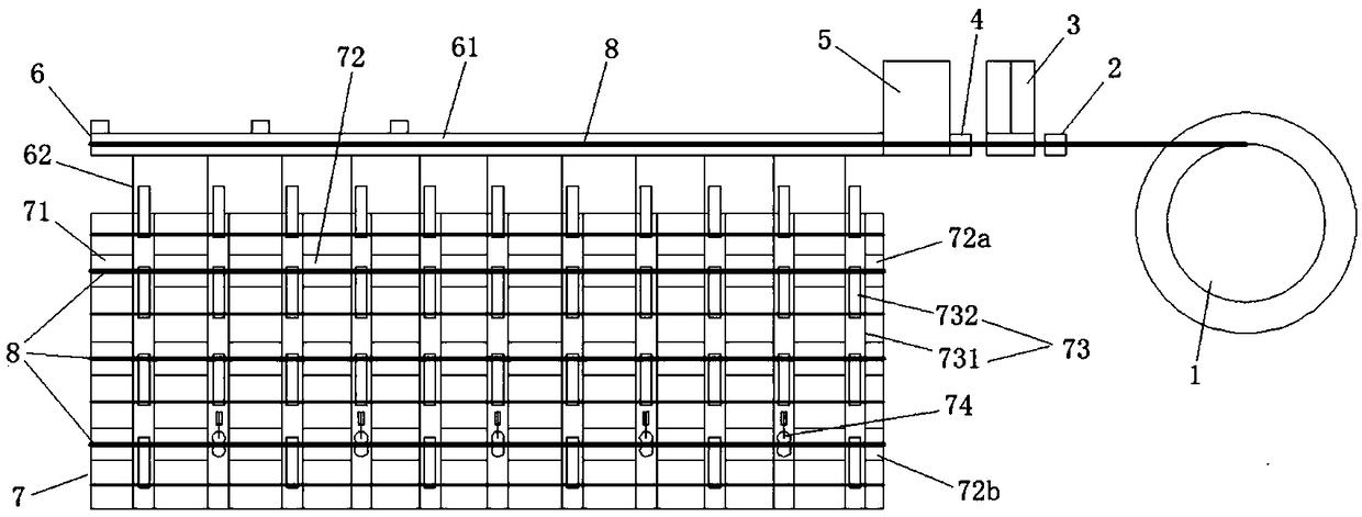
[0018] Such as figure 1 As shown, a preferred embodiment of a steel bar cutting and feeding device provided by the present invention includes a frame, a container turntable 1, a straightening mechanism 2, a traction mechanism 3, and a guide mechanism 4, which are sequentially arranged on the frame. Cutting mechanism 5, blanking mechanism 6, and discharging mechanism 7. The steel coil is placed on the turret 1, and the steel coil is pulle...


PUM


Abstract

The invention discloses a reinforcing steel bar cut-off and feeding device. The reinforcing steel bar cut-off and feeding device comprises a rack as well as a containing rotary table, a straighteningmechanism, a traction mechanism, a guide mechanism, a cut-off mechanism, a dropping material and a discharge mechanism which are sequentially arranged on the rack, wherein a reinforcing steel bar rollis placed on the containing rotary table; under traction action of the traction mechanism, reinforcing steel bars of the reinforcing steel bar roll are pulled out from the containing rotary table; after being straightened by the straightening mechanism, the reinforcing steel bars sequentially enter the guide mechanism, the cut-off mechanism and the dropping mechanism; when the reinforcing steel bars reach needed length of reinforcing steel bar sections, the cut-off mechanism cuts off the reinforcing steel bars, so that the cut-off reinforcing steel bar sections drop into the discharge mechanism through the dropping mechanism; and the discharge mechanism longitudinally or transversely feeds out the reinforcing steel bar sections, so that arrangement of related equipment is convenient.

Description

technical field [0001] The invention belongs to the technical field of pipe pile production, and more specifically relates to a steel bar cutting and feeding device. Background technique [0002] The reinforcement cage is formed by welding the main reinforcement and the stirrup. The main reinforcement is spaced apart from each other and parallel to form a ring-shaped column. The stirrup is wound and welded on the ring-shaped column-shaped main reinforcement according to the set pitch. The reinforcement cage is determined by the length of the main reinforcement. The main reinforcement is generally relatively thick. For the convenience of storage and transportation, the main reinforcement is generally about 12 meters long, and the length of the existing reinforcement cage is generally about 12 meters. [0003] In the production process of the main reinforcement, it is generally necessary to go through the process of steel coil feeding, straightening, cutting, and sending out. ...

Claims


Application Information

Patent Timeline
IPC IPC(8): B21F11/00B21F23/00
CPCB21F11/00B21F23/00
Inventor 许安春
Owner 广东华岩建材有限公司
Why Eureka
Try Eureka