
Coal mine hydraulic slag discharge drilling coal slag separation and conveying device

A conveying device and slag-water separation technology, which is applied in the directions of transportation and packaging, earth-moving drilling, underground transportation, etc., can solve the problems of increasing the labor cost of coal mine production, affecting the standardized image of the mine, and the labor intensity of cleaning work, and achieving a simple structure. , the effect of reducing labor intensity and quantity

Pending Publication Date: 2020-05-08
HENAN POLYTECHNIC UNIV
View PDF0 Cites 2 Cited by
  • Summary
  • Abstract
  • Description
  • Claims
  • Application Information

AI Technical Summary

Problems solved by technology

During the construction process, a large amount of coal slag was washed out of the borehole by water and accumulated in the roadway, which brought great inconvenience to the operation of drilling equipment and workers in the underground drilling site, and seriously affected the standardized image of the mine. The coal mine needs to arrange special Cleaners manually clean up the accumulated coal slag regularly, and use shovels to load the coal slag into the mine car. The cleaning work is labor-intensive and the working environment is harsh, which increases the labor cost of coal mine production.

Method used


Image

  • Coal mine hydraulic slag discharge drilling coal slag separation and conveying device
  • Coal mine hydraulic slag discharge drilling coal slag separation and conveying device
  • Coal mine hydraulic slag discharge drilling coal slag separation and conveying device

Examples


Embodiment Construction

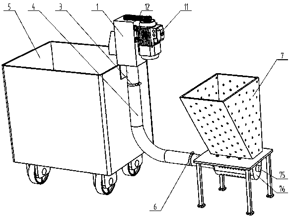
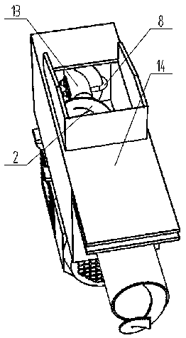
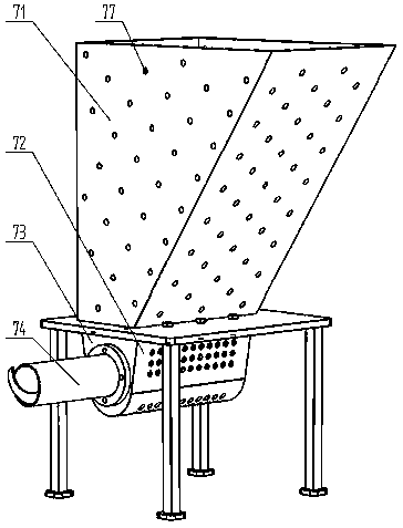
[0014] Such as figure 1 , figure 2 , image 3 , Figure 4 with Figure 5 As shown, the coal mine hydraulic slag discharge drilling coal slag separation conveying device includes a driving unloading part 1, a flexible shaftless spiral blade 2, a rubber hose 4 and a slag-water separation collection box 7; wherein, the driving unloading part 1 is composed of Power source 11, belt transmission mechanism 12, drive shaft 13 and discharge chute 14; slag-water separation collection box 7 consists of sieve plate funnel 71, U-shaped collection chute 72, side plate 73, support side plate 76, connecting pipe 74 and end shaft 75 form.

[0015] The discharge chute 14 of the drive discharge part 1 is composed of a rectangular trough 146, a discharge port 142, a transition pipe 144 and a fixed slot 143; the center position of the top plate 141 of the rectangular trough 146 along the length direction has The shaft hole 147, the transition tube 144 runs through the center of the bottom pl...


PUM


Abstract

The invention discloses a coal mine hydraulic slag discharge drilling coal slag separation and conveying device. The coal mine hydraulic slag discharge drilling coal slag separation and conveying device comprises a driving discharging part, a flexible shaftless spiral blade, a rubber hose and a slag water separation aggregate box; the driving discharging part is composed of a power source, a belttransmission mechanism, a driving shaft and a discharging groove; the slag water separation aggregate box is composed of a sieve plate funnel, an U-shaped aggregate groove, a side plate, a supportingside plate, a connecting pipe and an end shaft; the two ends of the flexible shaftless spiral blade are correspondingly and fixedly connected with the driving shaft and the end shaft; and the rubber hose sleeves the flexible shaftless spiral blade, and the two ends of the rubber hose are correspondingly and fixedly connected with the discharging groove and the connecting pipe of the slag water separation aggregate box. According to the coal mine hydraulic slag discharge drilling coal slag separation and conveying device, automatic separation of the coal slag and water can be achieved during the hydraulic slag discharge and drilling, the collected coal slag is automatically conveyed into a mine car, the conveying path can be bent, the equipment layout is flexible, the deposition of the coalslag in an underground roadway is avoided, the number of the coal slag cleaning personnel is decreased, the labor intensity of workers is lowered, and the working efficiency of the coal slag cleaningis improved.

Description

technical field [0001] The invention relates to the technical field of coal slag cleaning for hydraulic slag discharge drilling in coal mines. In particular, it relates to an automatic coal slag separation and conveying device for hydraulic slag discharge drilling in coal mines. Background technique [0002] The drilling technology of hydraulic slag removal is widely used in the construction of geological exploration drilling, gas drainage drilling, bolt support drilling and other engineering constructions in underground coal mines. During the construction process, a large amount of coal slag was washed out of the borehole by water and accumulated in the roadway, which brought great inconvenience to the operation of drilling equipment and workers in the underground drilling site, and seriously affected the standardized image of the mine. The coal mine needs to arrange special Cleaners manually clean up the accumulated coal slag regularly, and use shovels to load the coal sl...

Claims


Application Information

Patent Timeline
IPC IPC(8): E21B21/06E21F13/00
CPCE21B21/065E21B21/066E21F13/00
Inventor 韩晓明李钊李国栋李学成李永林宋松楠陈喜庆周磊
Owner HENAN POLYTECHNIC UNIV
Learn More