
Built-in mechanical direct-drive PTO double-floater type wave power generation device

A double-float type power generation device technology, applied in ocean energy power generation, mechanical equipment, hydropower generation, etc., can solve problems such as difficulty in ensuring continuity of power generation, high cost, poor stability, etc., and achieve high energy transfer efficiency, prolong life, Simple installation and little effect

Pending Publication Date: 2022-03-01
JIANGSU UNIV OF SCI & TECH
View PDF0 Cites 0 Cited by
  • Summary
  • Abstract
  • Description
  • Claims
  • Application Information

AI Technical Summary

Problems solved by technology

The existing oscillating buoy type wave power generation device is difficult to ensure the continuity of power generation during the reversing process, the stability is poor, and the structure is complex and expensive
PTO is in direct contact with seawater, easy to corrode and difficult to maintain

Method used


Image

  • Built-in mechanical direct-drive PTO double-floater type wave power generation device
  • Built-in mechanical direct-drive PTO double-floater type wave power generation device
  • Built-in mechanical direct-drive PTO double-floater type wave power generation device

Examples


Embodiment Construction

[0020] The technical solution of the present invention will be further described below in conjunction with the accompanying drawings.

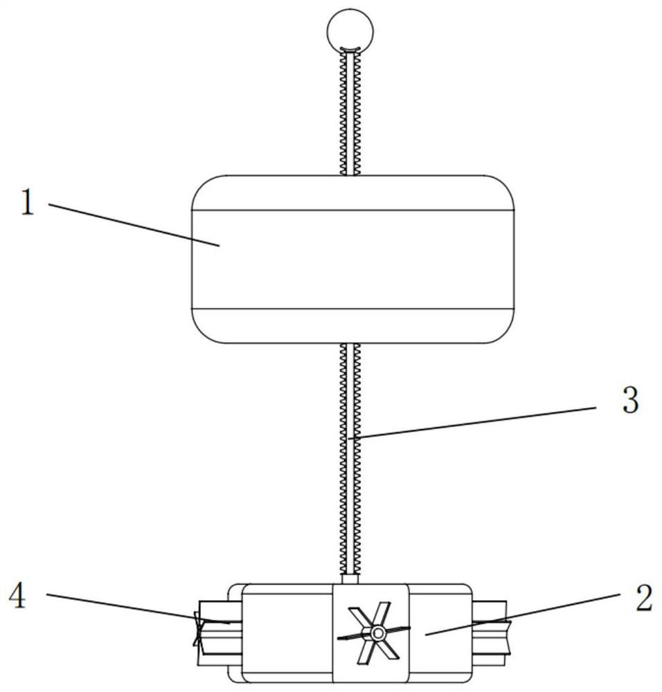
[0021] Such as figure 1 In the shown embodiment, it mainly includes a first float 1, a second float 2, a transmission rack 3, and a turbofan 4; the first float 1 and the second float 2 are connected through a transmission rack 3; the transmission rack 3 is used as a The track for the vertical relative movement and lifting of the float is slidingly connected with the first float 1, and the second float 2 is fixedly connected. The outer wall of the second float 2 is arranged with four sets of turbofans 4 along the circumference, and the turbofans 4 are driven by the internal settings. generator work.

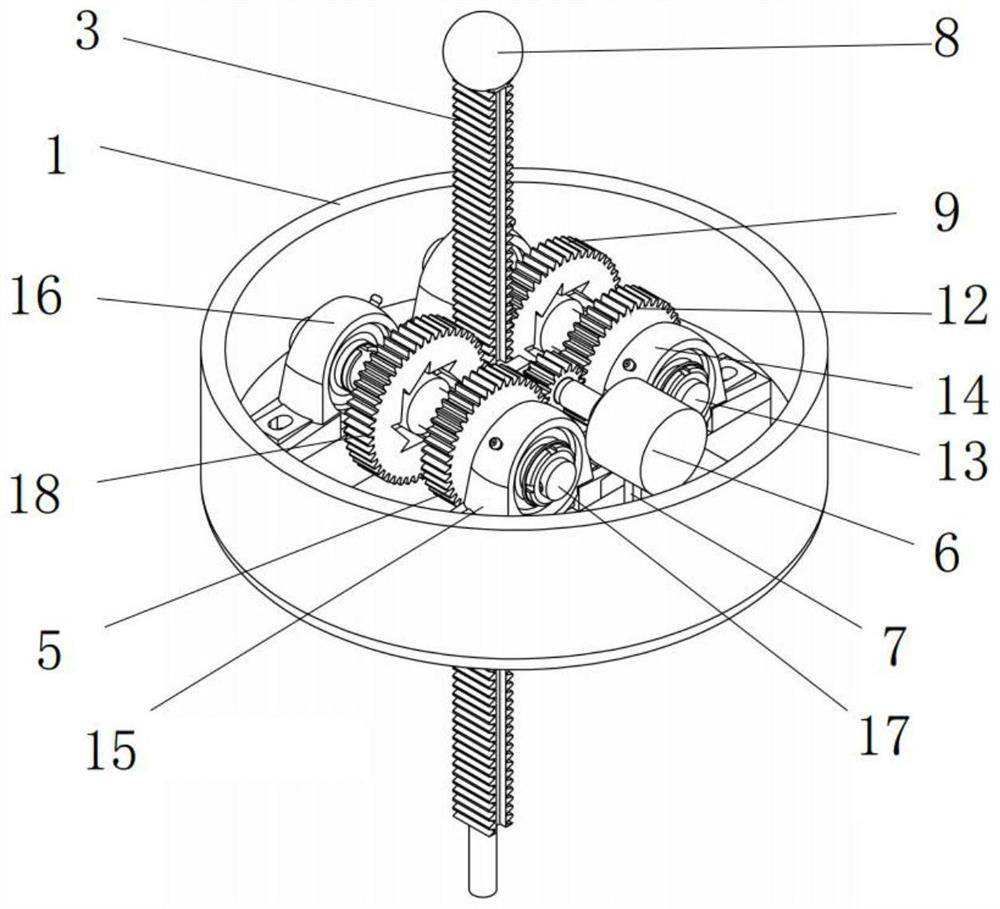
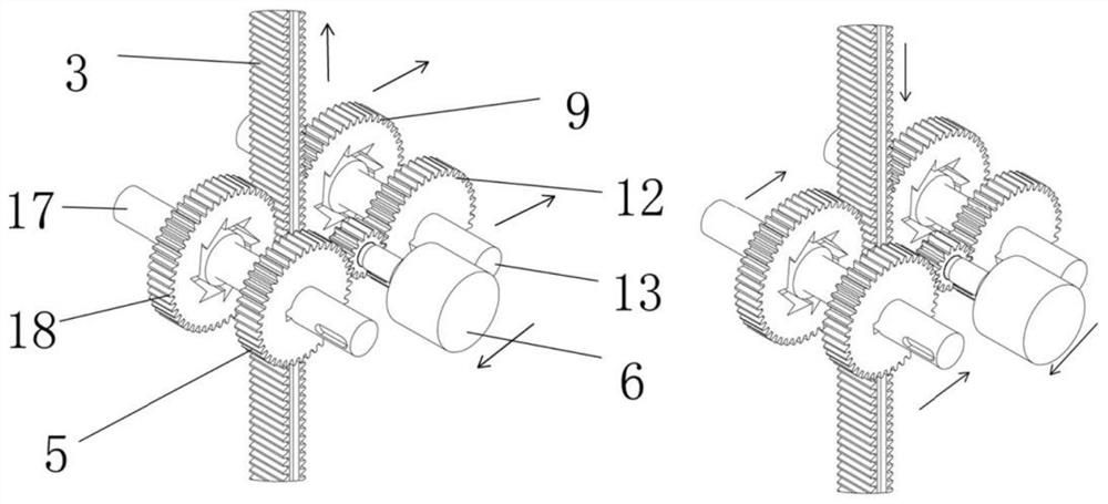
[0022] figure 2 It is a structural schematic diagram of the first float 1 and the shaft generator (PTO) transmission system. There are straight teeth on both sides of the transmission rack 3, which are respectively meshed with the first ratchet...


PUM


Abstract

The invention discloses a built-in mechanical direct-drive PTO double-floater type wave power generation device which comprises a first floater and a second floater, the first floater and the second floater are connected through a transmission rack and are hollow floaters, the first floater is in sliding connection with the transmission rack, and the second floater is in sliding connection with the transmission rack. A bearing, a generator and a transmission gear meshed with the transmission rack are arranged in the second floater, the transmission gear set is connected with the generator through a transmission assembly and drives the generator to generate electricity, the second floater is fixedly connected with the transmission rack, and a turbofan is arranged on the outer wall of the second floater and connected with the generator arranged in the second floater. The structure is simple and reliable, the utilization rate of wave energy can be increased, seawater corrosion to a transmission system is reduced, the service life of the transmission system is prolonged, the maintenance frequency is reduced, and the transmission system is simple in structure and high in energy transmission efficiency.

Description

technical field [0001] The invention relates to a floater type wave energy generating device, in particular to a floater type wave energy generating device which utilizes wave energy efficiently and is easy to maintain. Background technique [0002] With the continuous development of human society and the world economy, traditional energy sources are increasingly scarce, the ecological environment is seriously polluted and destroyed, and the use of large-scale fossil fuels has caused serious ecological and environmental problems. Under such circumstances, human beings gradually set their sights on the vast field of ocean energy. Wave energy is known as the highest-grade ocean energy due to its advantages of wide distribution, high energy flow density, less time limit, and low development difficulty. The research on its conversion device has increasingly become a hot issue in the world today. [0003] Compared with traditional energy resources, ocean energy resources will no...

Claims


Application Information

Patent Timeline
IPC IPC(8): F03B13/18F03B11/00F03B11/06F16H19/04
CPCF03B13/1815F03B11/00F03B11/06F16H19/043Y02E10/30Y02E10/20
Inventor 李冬琴张宇周利张锋陈文文马家泰
Owner JIANGSU UNIV OF SCI & TECH
Learn More