Slurry retaining wall drilling sediment treatment device for building pile foundations

A mud protection wall and treatment device technology, which is applied in construction, sheet pile walls, and foundation structure engineering, can solve the problems of inconvenient use of drilling sediment treatment equipment, reduced cleaning effect of sediment treatment equipment, and incomplete cleaning of drilling sediment, etc. Achieve the effects of simple structure, improved sediment treatment efficiency, and improved sealing

Active Publication Date: 2018-12-07
盐城市双强管桩有限公司
View PDF6 Cites 1 Cited by
  • Summary
  • Abstract
  • Description
  • Claims
  • Application Information

AI Technical Summary

Problems solved by technology

[0002] The depth, diameter, position and shape of the drilled hole are directly related to the quality of the pile and the straightness of the pile body. When the final hole inspection fully meets the design requirements, it is necessary to clean the bottom of the hole to avoid mud sedimentation after too long a time interval and cause drilling damage. For the phenomenon of collapse, it is more common to use a drilling sediment treatment device to clean up the sediment in the hole. The existing drilling sediment treatment device for mud wall protection for building pile foundations has certain disadvantages in use, and the drilling sediment is not cleaned thoroughly. The cleaning effect of the sediment treatment device is reduced, and at the same time, the sediment is easy to block the pipe of the suction dredge in the process of blowing out, which brings inconvenience to the use of the drilling sediment treatment device

Method used


Image

  • Slurry retaining wall drilling sediment treatment device for building pile foundations
  • Slurry retaining wall drilling sediment treatment device for building pile foundations

Examples


Embodiment Construction

[0018] The following will clearly and completely describe the technical solutions in the embodiments of the present invention with reference to the accompanying drawings in the embodiments of the present invention. Obviously, the described embodiments are only some, not all, embodiments of the present invention.

[0019] In describing the present invention, it should be understood that the terms "upper", "lower", "front", "rear", "left", "right", "top", "bottom", "inner", " The orientation or positional relationship indicated by "outside", etc. is based on the orientation or positional relationship shown in the drawings, and is only for the convenience of describing the present invention and simplifying the description, rather than indicating or implying that the referred device or element must have a specific orientation, so as to Specific orientation configurations and operations, therefore, are not to be construed as limitations on the invention.

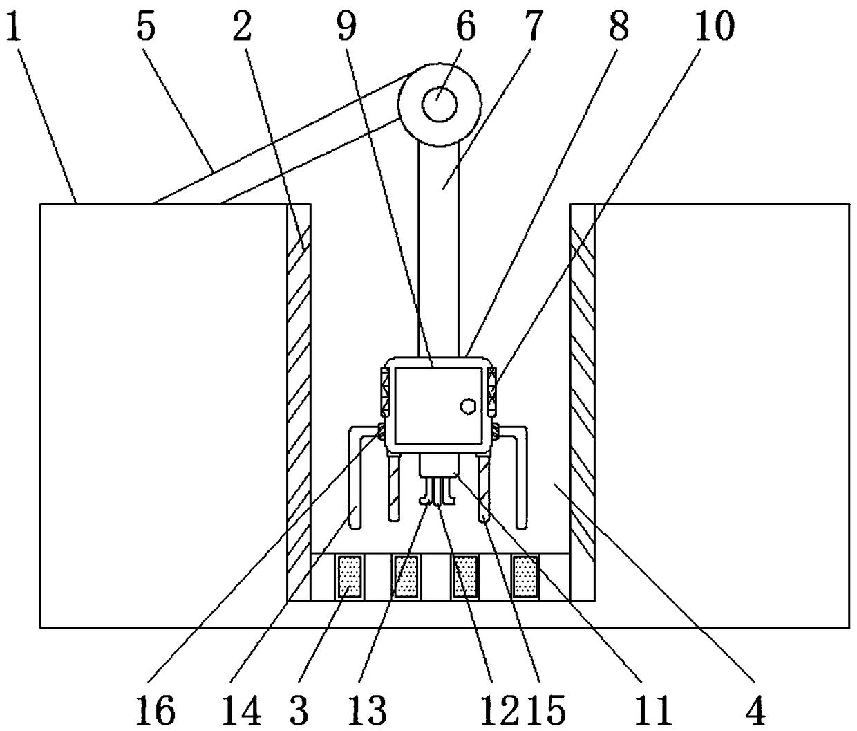
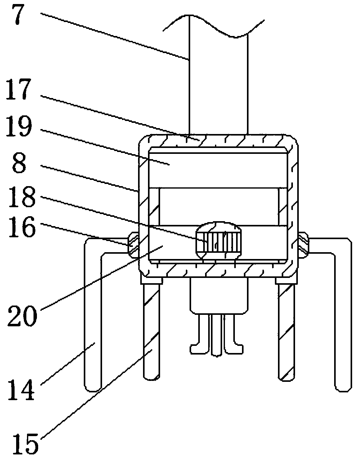
[0020] refer to Figure ...


PUM


Abstract

The invention discloses a slurry retaining wall drilling sediment treatment device for building pile foundations. The slurry retaining wall drilling sediment treatment device comprises a building foundation and a first mechanical arm, wherein retaining walls are fixedly installed at the two ends of the inner surface of the building foundation, drilling holes are formed in the lower portion insidethe building foundation, a rotating disc is arranged at one end of the first mechanical arm, and a second mechanical arm is arranged at the lower end of the rotating disc; a device shell is fixedly installed at the lower end of the second mechanical arm, a maintenance door is movably installed on the front surface of the device shell, a hydraulic lifting column is arranged at the lower end of thedevice shell, and an air blowing straight pipe is fixedly installed at the middle of the lower end of the hydraulic lifting column; and the two sides of the lower end of the hydraulic lifting column are each provided with an air blowing branch pipe, and the two sides of the lower end of the device shell are each provided with a dredging pipe. The slurry retaining wall drilling sediment treatment device for the building pile foundations is simple in structure, and lifting of the device can be controlled; and meanwhile, sediments in holes can be blown out in all directions, the sediments can bewetted, slurry can be pumped out, and the sediment treatment efficiency can be improved.

Description

technical field [0001] The invention relates to the technical field of building construction, in particular to a mud protection wall drilling sediment treatment device for building pile foundations. Background technique [0002] The depth, diameter, position and shape of the drilled hole are directly related to the quality of the pile and the straightness of the pile body. When the final hole inspection fully meets the design requirements, it is necessary to clean the bottom of the hole to avoid mud sedimentation after too long a time interval and cause drilling damage. For the phenomenon of collapse, it is more common to use a drilling sediment treatment device to clean up the sediment in the hole. The existing drilling sediment treatment device for mud wall protection for building pile foundations has certain disadvantages in use, and the drilling sediment is not cleaned thoroughly. The cleaning effect of the sediment treatment device is reduced, and at the same time, the ...

Claims


Application Information

Patent Timeline
Patent Type & Authority Applications(China)
IPC IPC(8): E02D13/08E21B21/16
CPCE02D13/08E21B21/16
Inventor 程恭正
Owner 盐城市双强管桩有限公司
Why Eureka
Try Eureka