
Jet aero-engine vector nozzle and aero-engine

An aero-engine and vector nozzle technology, which is applied in the direction of machines/engines, jet propulsion devices, etc., can solve the problem of changing the flight attitude of the aircraft, the limitation of the use range of the aero-engine vector nozzle, and the inability to control the air flow of the vector nozzle to close and open the vector Nozzle and other problems, to achieve the effect of a wide area

Active Publication Date: 2020-11-10
珠海市蓝鹰贸易有限公司
View PDF6 Cites 1 Cited by
  • Summary
  • Abstract
  • Description
  • Claims
  • Application Information

AI Technical Summary

Problems solved by technology

[0004] (2) The current vectoring nozzles of jet aeroengines can only change the direction of the ejected airflow, up, down, left, and right, and cannot control the air flow of the vectoring nozzles or close and open the vectoring nozzles, so that the direction of the vectoring nozzles of the aeroengines The scope of use is very limited, and it is impossible to change the flight attitude of the aircraft by controlling the amount of air ejected from different vector nozzles of the aircraft
[0005] (3) At present, only one vectoring nozzle can be installed on each jet aircraft engine. It is impossible to install several pressure chambers on the aircraft, which can be closed and opened at the same time, and the jet flow can be adjusted. The vectoring nozzle that swings left and right prevents us from producing a jet-type vertical lift aircraft that is easy to change the attitude of the aircraft and easy to control

Method used


Image

  • Jet aero-engine vector nozzle and aero-engine
  • Jet aero-engine vector nozzle and aero-engine
  • Jet aero-engine vector nozzle and aero-engine

Examples


Embodiment Construction

[0032] In order to make the object, technical solution and advantages of the present invention clearer, the present invention will be further described in detail below in conjunction with the accompanying drawings and embodiments. It should be understood that the specific embodiments described here are only used to explain the present invention, not to limit the present invention.

[0033] Such as Figure 1-6 Shown:

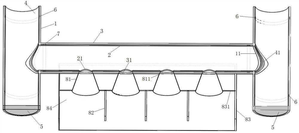
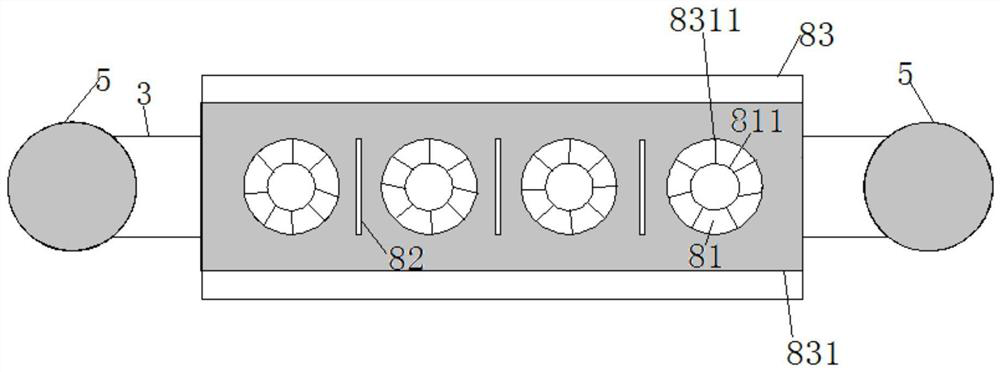
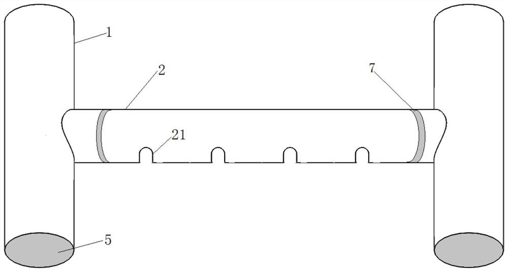
[0034] A jet aircraft engine vectoring nozzle, comprising a high-pressure air intake pipe 1, a valve pipe 4, a valve control assembly 5, an inner jet pipe 2, an outer jet pipe 3, a first sealing ring 6 and an outer nozzle assembly, and a high-pressure air intake pipe 1 is provided with a first circular hole 11, the valve pipe 4 is nested in the high-pressure air intake pipe 1 and a second circular hole 41 is provided at a position corresponding to the first circular hole 11, and the valve control assembly 5 is arranged at the high-pressure air intake pipe 1 The...


PUM


Abstract

The invention discloses an jet aircraft engine vector nozzle capable of changing the direction of the jet air flow up and down and left and right, continuously adjusting the volume of the jet air flowand controlling the jet air flow through opening and closing. According to the jet aircraft engine vector nozzle, the design idea of an original jet aircraft engine vector nozzle is changed, a brand-new design scheme is adopted, the shape of the original jet aircraft engine vector nozzle is changed daringly, the process is greatly simplified compared with the process of the original design, the production and manufacturing difficulty is also greatly reduced; the novel jet aircraft engine vector nozzle is invented so that a pressure cavity can be installed on an aircraft by people, high-pressure airflow generated by the aircraft engine can be sprayed into the pressure cavity of the aircraft, then the airflow sprayed by all the novel jet aircraft engine vector nozzles connected to the pressure cavity of the aircraft is closed, opened and continuously adjusted correspondingly, so that the purpose of more easily controlling the attitude of the aircraft is achieved, and then the jet vertical-lifting aircraft which can be driven by a common person just like an automobile is produced.

Description

technical field [0001] The invention belongs to the technical field of jet aeroengines, in particular to a jet aeroengine vectoring nozzle and an aeroengine. Background technique [0002] At present, the known jet aeroengine vectoring nozzle is to set a mechanical device at the position of the tail nozzle that can control the swing of the tail nozzle up and down, so that all the high-pressure airflow generated by the engine is ejected through the tail nozzle. Up, down, left, and right directions, thereby correspondingly changing the direction in which the jet aeroengine generates thrust to the aircraft. Such aero-engine vectoring nozzle obviously has the following deficiencies: [0003] (1) The high-pressure airflow produced by each jet aircraft engine at present is all ejected through a single tail nozzle, and the air flow is huge, and the shape of the tail nozzle is all circular, so it is necessary to control the circle where the huge amount of high-pressure airflow is ej...

Claims


Application Information

Patent Timeline
Patent Type & Authority Patents(China)
IPC IPC(8): F02K1/00F02K1/78
CPCF02K1/00F02K1/78
Inventor 张鸿元
Owner 珠海市蓝鹰贸易有限公司
Learn More