Pneumatic feedback type automobile shock suppressing and absorbing device

A shock absorber and feedback technology, applied in the direction of shock absorbers, gas shock absorbers, spring/shock absorbers, etc., can solve the problems of single function, difficult to control, energy storage that cannot vibrate, etc., and achieve structural The effect of compact design, stable shock absorption and safe limit

Active Publication Date: 2018-12-07
北京盒子智行科技有限公司
View PDF9 Cites 1 Cited by
  • Summary
  • Abstract
  • Description
  • Claims
  • Application Information

AI Technical Summary

Problems solved by technology

[0002] At present, the existing shock absorption technology uses the shock absorber to complete the absorption and shock absorption of the impact force, and uses the damper to accelerate the attenuation of the vibration energy. The different impact forces generated under different working conditions are only reduced by a single shock absorption method. The impact energy is absorbed, and the shock absorption process cannot be replicated. It has a single function and cannot effectively convert and utilize the impact energy; in addition, the existing shock absorption technology cannot store the vibration energy, resulting in a waste of energy.
[0003] In order to solve the above-mentioned problems, the present invention is proposed, which overcomes the problems of the currently used automobile shock absorbing equipment, because the energy generated in the shock absorbing process is ignored due to the simple use of spring shock absorbers, resulting in waste of energy, etc. Shock absorbing equipment, when dealing with large-scale shock absorbing operations, often adopts an active shock absorbing structure, resulting in additional energy consumption, but the shock absorbing process cannot be copied, is difficult to control, and has many problems such as shock absorbing energy consumption, so that the present invention It has the advantages of compact structure design, safe limit, stable operation, energy collection by air pressure limit, high efficiency, more stable shock absorption, etc.

Method used


Image

  • Pneumatic feedback type automobile shock suppressing and absorbing device
  • Pneumatic feedback type automobile shock suppressing and absorbing device
  • Pneumatic feedback type automobile shock suppressing and absorbing device

Examples


Embodiment Construction

[0020] The following will clearly and completely describe the technical solutions in the embodiments of the present invention with reference to the accompanying drawings in the embodiments of the present invention. Obviously, the described embodiments are only some, not all, embodiments of the present invention. Based on the embodiments of the present invention, all other embodiments obtained by persons of ordinary skill in the art without making creative efforts belong to the protection scope of the present invention.

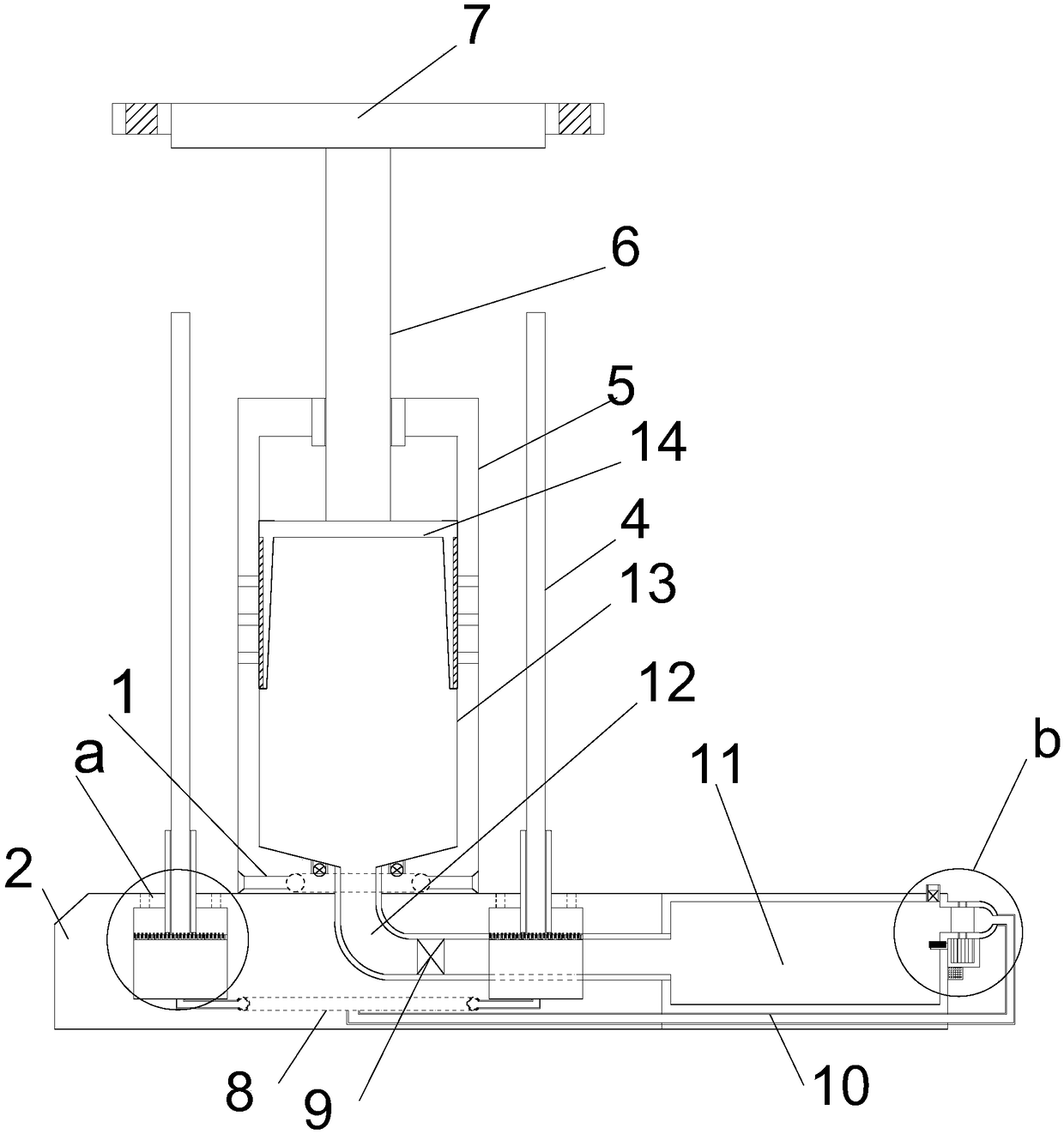
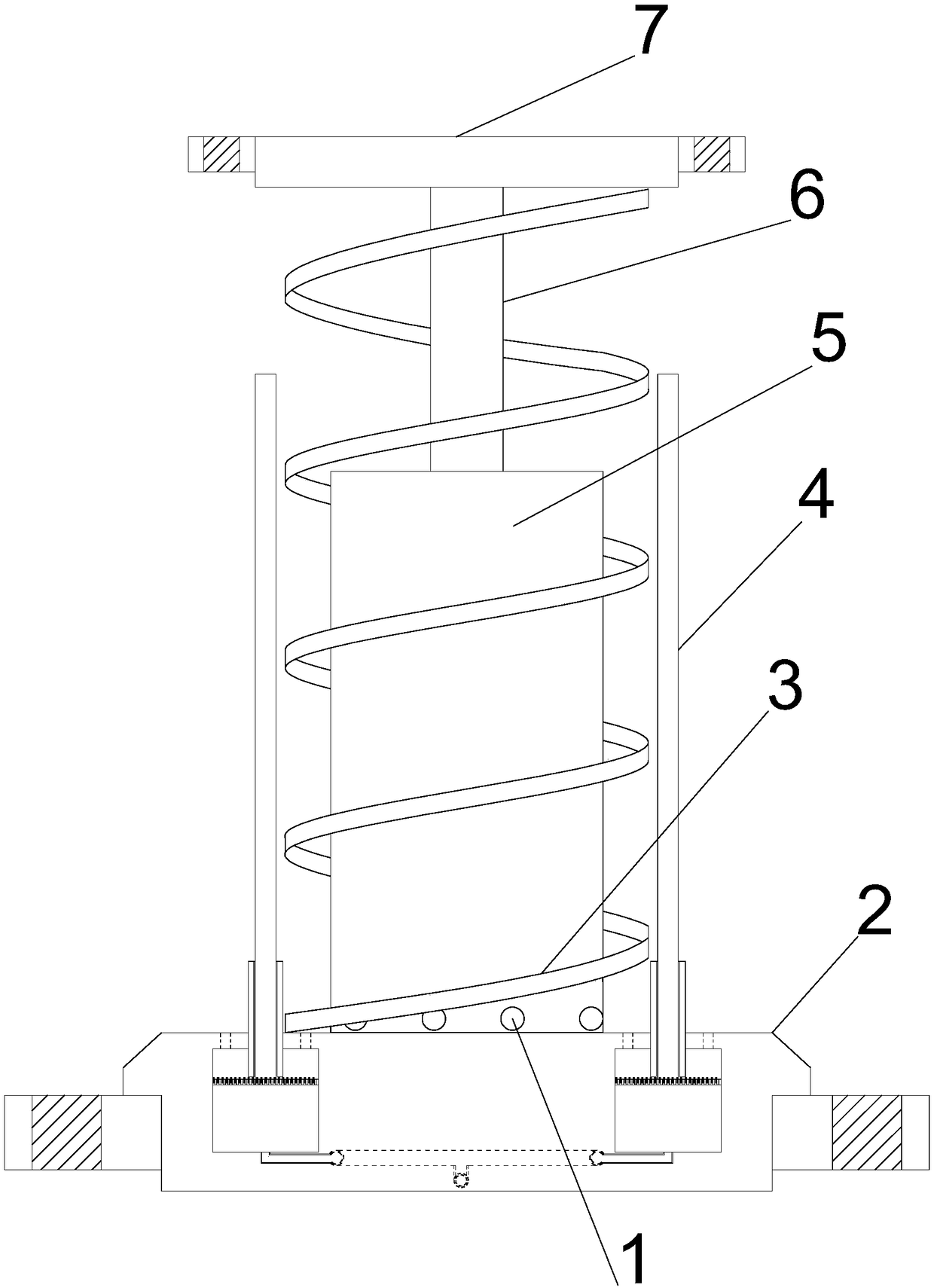
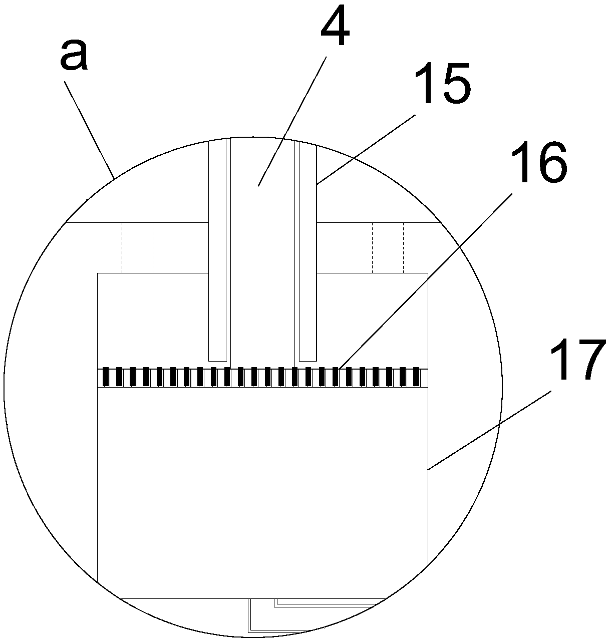
[0021] see Figure 1~6 , in an embodiment of the present invention, a pneumatic feedback type automotive damping device, including a support installation plate 2, the upper middle position of the support installation plate 2 is vertically provided with a support installation cylinder 5, and the inside of the support installation cylinder 5 The middle position is vertically inlaid with a damping damping cylinder 13, and the upper middle position of the supporti...


PUM


Abstract

The invention discloses a pneumatic feedback type automobile shock suppressing and absorbing device. The device comprises a support mounting disc. A support mounting barrel is arranged vertically upwards in the middle of the upper end of the support mounting disc. A shock suppressing and absorbing cylinder is vertically embedded in the middle of the interior of the support mounting barrel. A lifting shock absorbing column is vertically arranged in the middle of the upper end of the support mounting barrel through an embedded guide barrel and is matched with the shock suppressing and absorbingcylinder. The lower end of the lifting shock absorbing column stretches into the shock suppressing and absorbing cylinder and is provided with a pneumatic piston barrel horizontally in a matched mode,and a plurality of flow guide inlet holes are uniformly formed in the middle of the shock suppressing and absorbing cylinder in a penetrating mode. Four groups of limit lifting columns are verticallyarranged in the position, below the support mounting barrel, of the support mounting disc at equal angles. A high-pressure cylinder is arranged horizontally on the right side of the support mountingdisc. A pneumatic feedback shock absorbing structure is arranged at the right end of the high-pressure cylinder. The pneumatic feedback type automobile shock suppressing and absorbing device has the advantages that the structural design is compact, limit is safe, operating is stable, the air pressure is limited, energy is collected, the efficiency is high, and shock absorbing is more stable.

Description

technical field [0001] The invention relates to an automobile energy-saving device, in particular to a pneumatic feedback type automobile restraining and shock absorbing device. Background technique [0002] At present, the existing shock absorption technology uses the shock absorber to complete the absorption and shock absorption of the impact force, and uses the damper to accelerate the attenuation of the vibration energy. The different impact forces generated under different working conditions are only reduced by a single shock absorption method. The impact energy is absorbed, and the shock absorption process cannot be replicated, its function is single and the energy of the impact cannot be effectively converted and utilized; in addition, the existing shock absorption technology cannot store the energy of the vibration, resulting in a waste of energy . [0003] In order to solve the above-mentioned problems, the present invention is proposed, which overcomes the problem...

Claims


Application Information

Patent Timeline
Patent Type & Authority Applications(China)
IPC IPC(8): F16F9/02F16F9/34F16F9/512F16F9/54B60G13/00
CPCB60G13/00F16F9/0209F16F9/029F16F9/34F16F9/512F16F9/54F16F2230/08F16F2230/18
Inventor 卢若望
Owner 北京盒子智行科技有限公司
Why Eureka
Try Eureka