
Cleanable spiral heat exchanger

A spiral heat exchanger technology, applied in the field of cleanable spiral heat exchangers, can solve the problems of high energy consumption, poor heat exchange effect, damage to the heat exchanger and can not be used, so as to achieve simple operation and reduce the difficulty of washing , The effect of reducing the difficulty of cleaning

Active Publication Date: 2018-12-07
安徽省碧绿春生物科技有限公司
View PDF7 Cites 0 Cited by
  • Summary
  • Abstract
  • Description
  • Claims
  • Application Information

AI Technical Summary

Problems solved by technology

Once the channel is blocked, the heat transfer effect is poor and the energy consumption is high, until the entire heat exchanger is damaged and cannot be used

Method used


Image

  • Cleanable spiral heat exchanger
  • Cleanable spiral heat exchanger
  • Cleanable spiral heat exchanger

Examples


Embodiment Construction

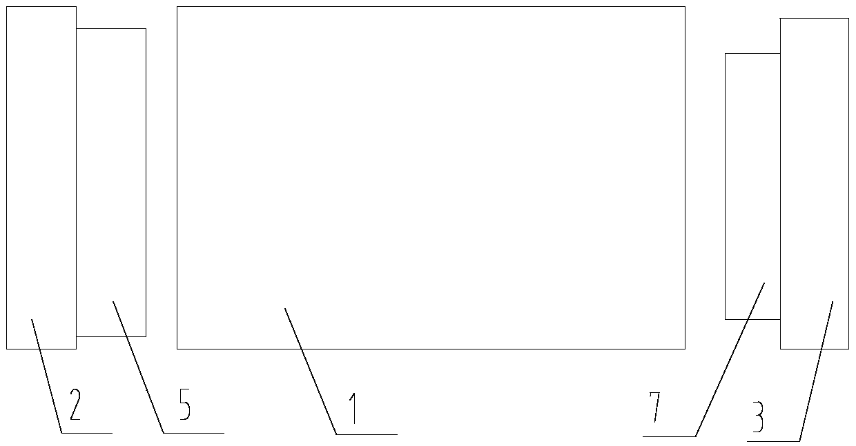
[0020] refer to figure 1 , a cleanable spiral heat exchanger proposed by the present invention includes a main body 1 , a first end cover 2 and a second end cover 3 .

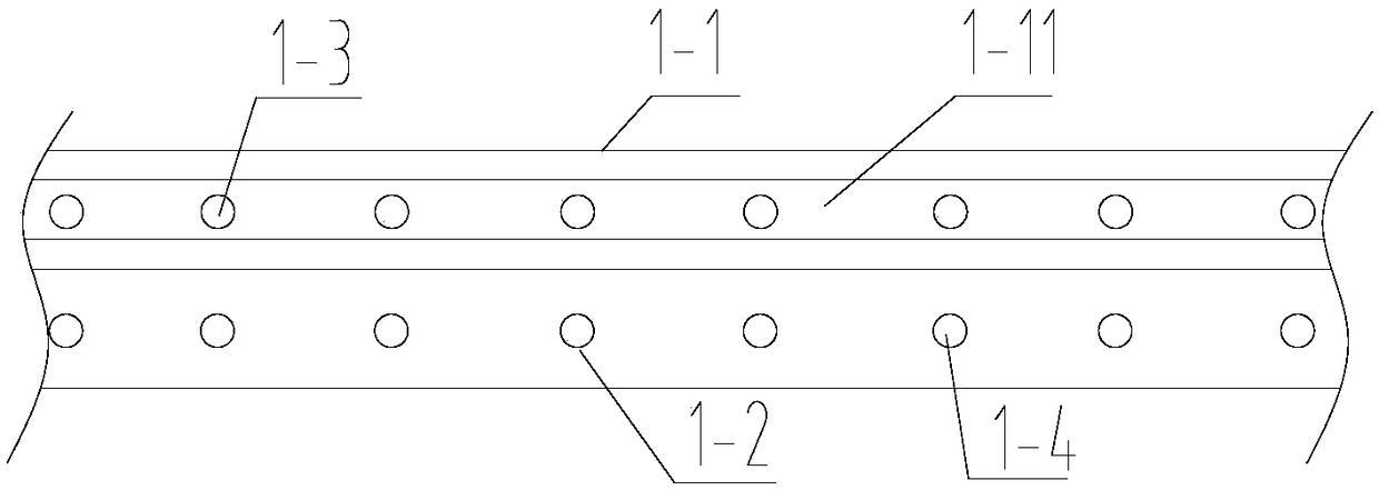
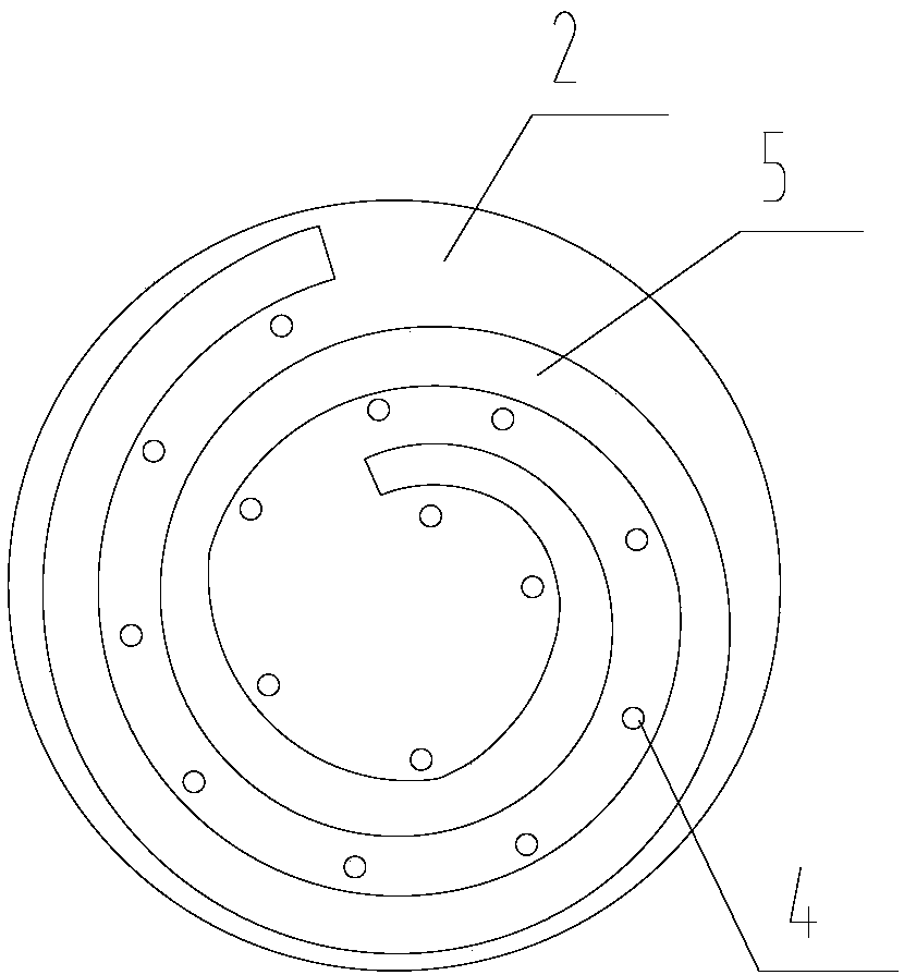
[0021] The main body 1 is formed by rolling the stacked first U-shaped groove plate 1-1 and the second U-shaped groove plate 1-2, and the first U-shaped groove plate 1-1 and the second U-shaped groove plate 1-2 The first spiral channel 1-11 and the second spiral channel are respectively formed after rolling. The bottom of the first U-shaped channel plate 1 - 1 is located at the first end of the main body 1 , and the bottom of the second U-shaped channel plate 1 - 2 is located at the second end of the main body 1 .

[0022] The bottom of the first U-shaped groove plate 1-1 is provided with a plurality of first through holes 1-12 distributed along the extending direction of the first spiral channel 1-11, and each first through hole 1-12 is equipped with a first One-way valve 1-3. The first one-way valve 1-3 is ...


PUM


Abstract

The invention provides a cleanable spiral heat exchanger. The cleanable spiral heat exchanger comprises a main body, a first end cover and a second end cover; the main body is wound by a first U-shaped groove plate and a second U-shaped groove plate, which are laminated; the first U-shaped groove plate and the second U-shaped groove plate respectively form a first spiral channel and a second spiral channel; the bottom of the first U-shaped groove plate is positioned at a first end of the main body; and the bottom of the second U-shaped groove plate is positioned at a second end of the main body. In the cleanable spiral heat exchanger, when the first spiral channel is blocked, the second end cover is only disassembled; then, a first cavity is inflated through an air supply mechanism, so that the inside of the first spiral channel can be flushed through a first air valve without disassembling the first end cover and emptying the second spiral channel, and the flushing difficulty is greatly reduced; and similarly, when the second spiral channel is blocked, the first end cover is only disassembled, and the second spiral channel is washed by air through the air supply mechanism and a second connecting head.

Description

technical field [0001] The invention relates to the technical field of spiral heat exchangers, in particular to a cleanable spiral heat exchanger. Background technique [0002] At present, domestic spiral plate heat exchangers have two channels, one for cooling liquid, referred to as channel A, and the other channel for feeding materials, referred to as channel B, both of which are fixed and welded. Once the channel is blocked, the heat exchange effect is poor and the energy consumption is high, until the entire heat exchanger is damaged and cannot be used. Contents of the invention [0003] Based on the technical problems in the background technology, the present invention proposes a cleanable spiral heat exchanger. [0004] A cleanable spiral heat exchanger proposed by the present invention includes a main body, a first end cover and a second end cover; [0005] The main body is formed by rolling the stacked first U-shaped groove plate and the second U-shaped groove pl...

Claims


Application Information

Patent Timeline
Patent Type & Authority Applications(China)
IPC IPC(8): F28D7/02F28F9/10F28G9/00
CPCF28D7/02F28F9/10F28G9/00
Inventor 董传宁杨银
Owner 安徽省碧绿春生物科技有限公司
Learn More