High-voltage DC circuit breaker current withstand test loop and method
A high-voltage DC, current-tolerant technology, applied in circuit breaker testing, instruments, measuring electricity, etc., can solve the problems of difficult to control the loading current time, imprecise real current simulation, etc. Accuracy, low operating costs
Active Publication Date: 2018-12-07
XJ ELECTRIC +2
View PDF13 Cites 1 Cited by
- Summary
- Abstract
- Description
- Claims
- Application Information
AI Technical Summary
Problems solved by technology
[0005] The purpose of the present invention is to provide a high-voltage DC circuit breaker current withstand test circuit and method, which are used to solve the problem that the imit
Method used
View moreImage
Smart ImageViewing Examples

Examples
 PUM
 Abstract
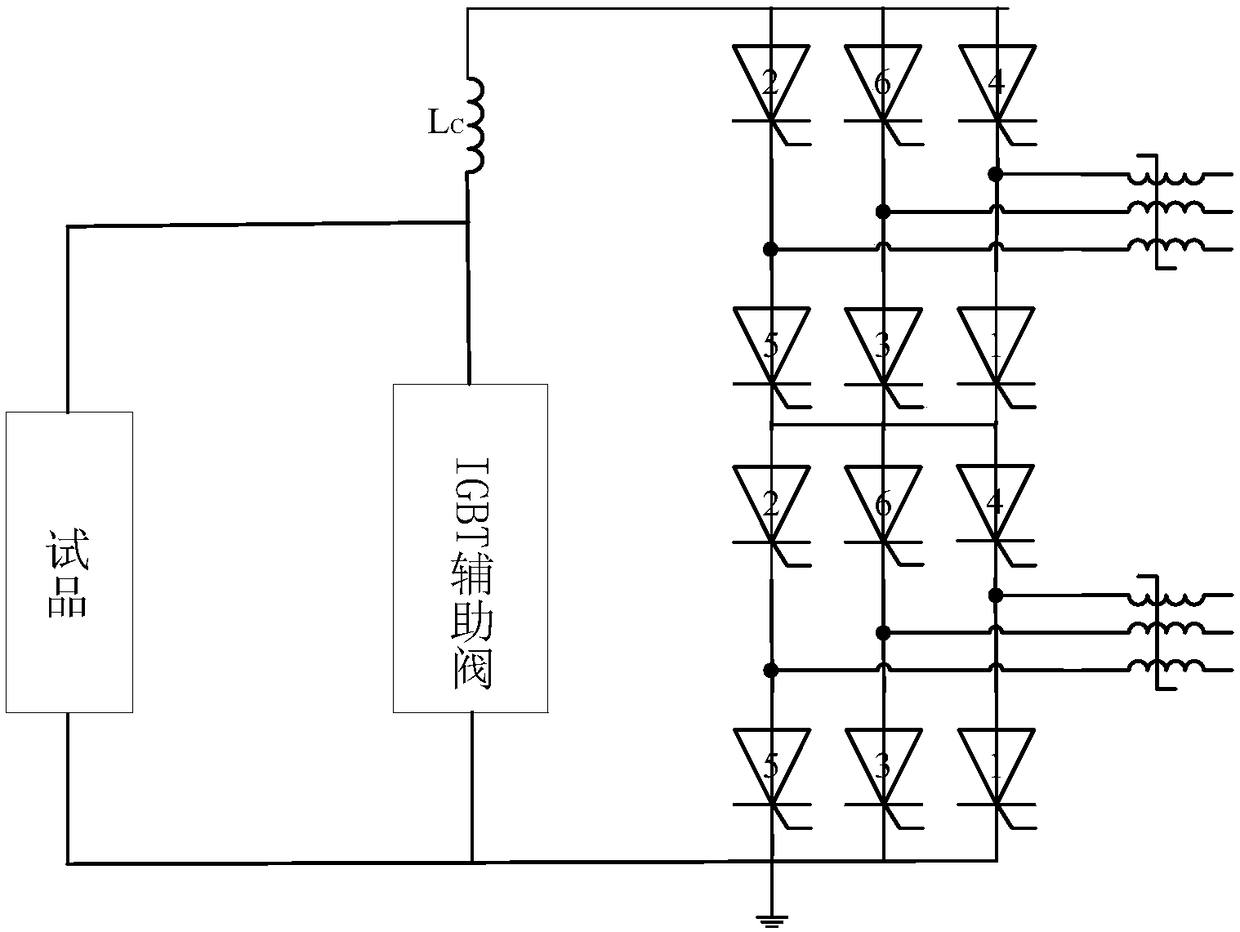
The invention relates to a high-voltage DC circuit breaker current withstand test loop and a high-voltage DC circuit breaker current withstand test method. The high-voltage DC circuit breaker currentwithstand test loop comprises a DC power supply, an electric reactor and a test branch circuit which are connected in series, wherein the test branch circuit is used for setting a DC circuit breaker sample serially, both ends of the test branch circuit are in parallel connection with an auxiliary switching valve branch circuit used for transferring a current in the test branch circuit, and the auxiliary switching valve branch circuit is provided with at least one fully-controlled switching device serially. Through parallelly connecting the auxiliary switching valve branch circuit and the testbranch circuit used for setting the DC circuit breaker sample in series, the current flowing through the test branch circuit is auxiliarily controlled by means of the auxiliary switching valve branchcircuit in the DC circuit breaker current test process, the test current of the DC circuit breaker sample is ensured to be relatively stable, the phenomenon that the test current changes slowly when the DC current is directly loaded to the DC circuit breaker sample by means of the electric reactor is avoided, the current loading time of the DC circuit breaker sample can be precisely controlled, and the precision of real current simulation and precision of tests are improved.
Description
technical field [0001] The invention relates to a current withstand test circuit and method of a high-voltage direct current circuit breaker, and belongs to the technical field of high-voltage direct current circuit breaker tests. Background technique [0002] HVDC transmission is a new type of power transmission developed in the 1950s. At present, there are about 100 DC transmission projects in the world, and there are more than 10 DC transmission projects in my country, with a total capacity of more than 18GW and a total transmission distance of more than 7000km. At present, China's power grid has entered an era of AC-DC complementarity. The continuous progress of DC transmission technology and its superiority in the development of large power grids have made my country's power grids face an unprecedented development situation. Since DC transmission has the characteristics of long transmission distance, large transmission capacity, and flexible control, etc., the DC transm...
Claims
Login to View More Application Information
Patent Timeline
 IPC IPC(8): G01R31/327
CPCG01R31/3272
Inventor 姚为正胡四全范彩云常忠廷才利存徐涛邱育林董岳
Owner XJ ELECTRIC