
Shift temporary storage circuit and display device

A technology of shifting temporary storage and shifting temporary storage unit, which is applied in information storage, static memory, static indicator, etc. It can solve the problem that the scanning signal cannot be completely turned off, the high level of the scanning signal is limited, and the reset time is long, etc. question

Active Publication Date: 2018-12-07
HKC CORP LTD
View PDF5 Cites 4 Cited by
  • Summary
  • Abstract
  • Description
  • Claims
  • Application Information

AI Technical Summary

Problems solved by technology

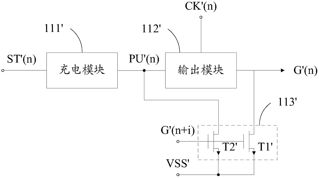
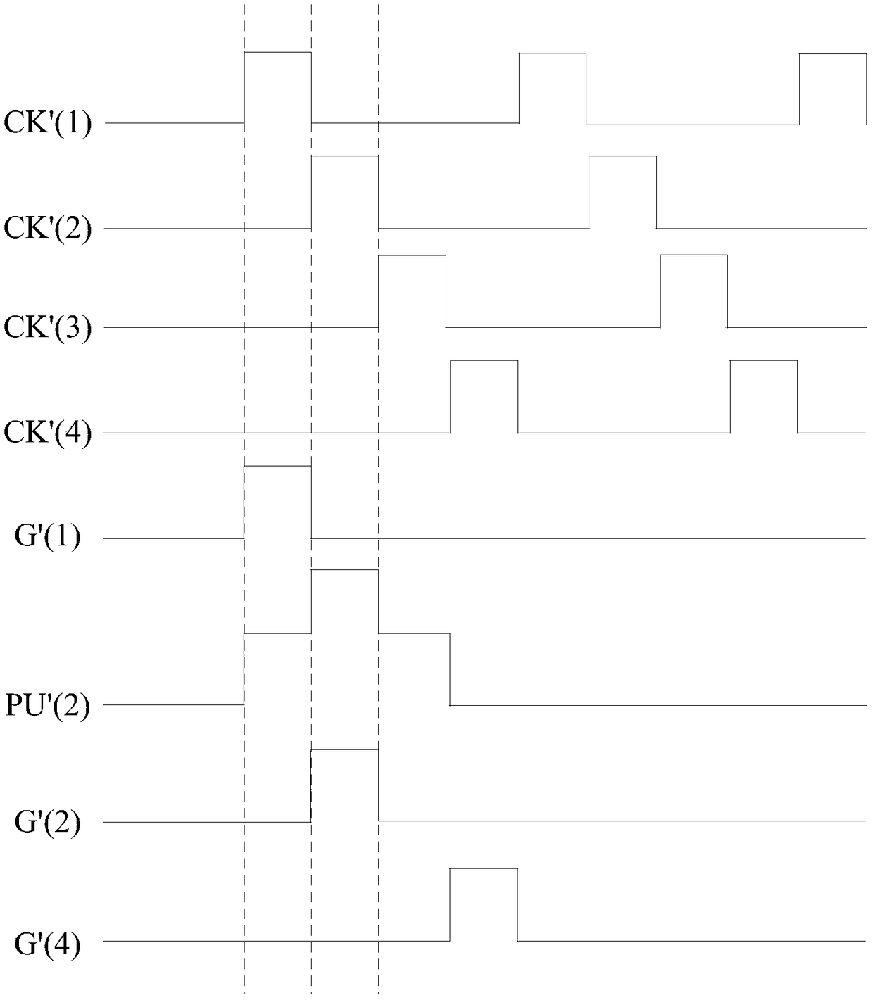
However, due to the limited high level of the scan signal output by the subsequent shift temporary storage unit, the reset time required for the pull-up point and the scan signal output terminal is often longer. When the reset is insufficient, the current shift temporary The scanning signal generated by the memory unit will be tailed, that is, the scanning signal cannot be completely turned off, which will lead to abnormal display screen

Method used


Image

  • Shift temporary storage circuit and display device
  • Shift temporary storage circuit and display device
  • Shift temporary storage circuit and display device

Examples


Embodiment Construction

[0024] The following will clearly and completely describe the technical solutions in the embodiments of the present invention with reference to the accompanying drawings in the embodiments of the present invention. Obviously, the described embodiments are only part of the embodiments of the present invention, not all of them. Based on the embodiments of the present invention, all other embodiments obtained by persons of ordinary skill in the art without creative efforts fall within the protection scope of the present invention.

[0025] It should be noted that if there is a directional indication (such as up, down, left, right, front, back...) in the embodiment of the present invention, the directional indication is only used to explain the position in a certain posture (as shown in the accompanying drawing). If the specific posture changes, the directional indication will also change accordingly.

[0026] In addition, if there are descriptions involving "first", "second" and ...


PUM


Abstract

The invention discloses a shift temporary storage circuit and a display device. The shift temporary storage circuit includes cascaded multistage shift temporary storage units. Each shift temporary storage unit includes a reset module. The reset signal input end of each reset module is electrically connected with the pull-up point of the shift temporary storage unit in the following stage. When thepull-up point and the scan signal output end of the shift temporary storage unit in the current stage are reset, the pull-up signal of the pull-up point of the shift temporary storage unit in the following state is in a high-level state. The technical solution of the invention is beneficial to shortening the reset time required by the shift temporary storage circuit, and avoids display screen anomaly caused by the tailing of the scan signal.

Description

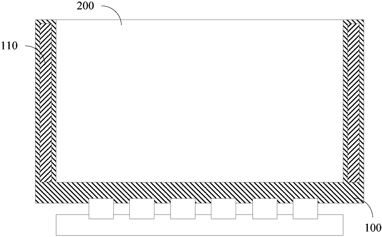
technical field [0001] The invention relates to the field of display technology, in particular to a shift register circuit and a display device. Background technique [0002] In order to adapt to the development of thinner, thinner frame and lower cost of display devices, Gate Drive on Array (GOA) is usually used to realize the output of line scanning signals at present. The integration is realized on the array substrate of the display device. The shift temporary storage circuit includes cascaded multi-level shift temporary storage units, and the pull-up points and scan signal output terminals of the shift temporary storage units at each level are under the action of the scanning signals output by the subsequent shift temporary storage units. is reset to the low state. However, due to the limited high level of the scan signal output by the subsequent shift temporary storage unit, the reset time required for the pull-up point and the scan signal output terminal is often lon...

Claims


Application Information

Patent Timeline
IPC IPC(8): G09G3/20G11C19/28
CPCG09G3/20G09G2310/0286G11C19/28
Inventor 何怀亮
Owner HKC CORP LTD
Learn More