Method for improving reactive power distribution of parallel inverters

A technology of power distribution and inverter, which is applied in the direction of output power conversion device, AC power input conversion to DC power output, electrical components, etc., can solve the problems of reactive power distribution deviation and parallel circulation, and achieve the improvement of reactive power The effect of power distribution

Active Publication Date: 2018-12-07
XIAN UNIV OF TECH
View PDF4 Cites 6 Cited by
  • Summary
  • Abstract
  • Description
  • Claims
  • Application Information

AI Technical Summary

Problems solved by technology

[0005] The purpose of the present invention is to provide a method for improving the reactive power distribution of parallel inverters, which solves the problem of reactive power distribution deviation and parallel circulating current caused by the impedance ratio matching of parallel inverter lines in the prior art

Method used


Image

  • Method for improving reactive power distribution of parallel inverters
  • Method for improving reactive power distribution of parallel inverters
  • Method for improving reactive power distribution of parallel inverters

Examples


Embodiment

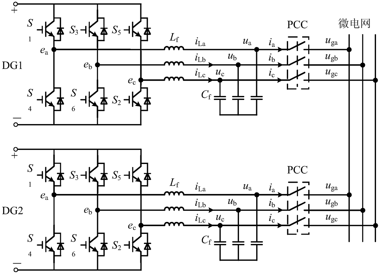
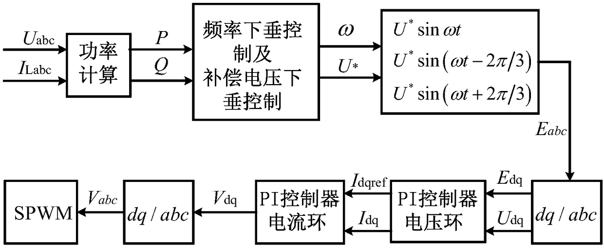
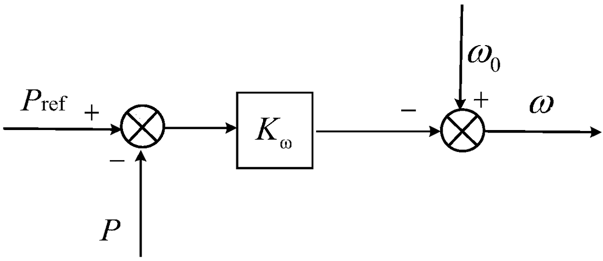
[0080] The present invention is a method for improving the reactive power distribution of parallel inverters, which combines figure 1 , figure 2 , The specific implementation is as follows:

[0081] Step 1. Calculate the output voltage U of the two inverters in the dq coordinate system respectively d1 , U q1 , U d2 , U q2 , Output current I d1 , I q1 , I d2 , I q2 , By the active power P 1 , P 2 Calculate the angular frequency ω 1 , Ω 2 , The specific implementation is as follows:

[0082] Step 1.1. Two inverters run in parallel with load, set the DC bus voltage U of the two inverters dc 700V, filter resistance R f , Inductance L f , Capacitance C f Respectively: 0.01Ω, 2mH, 50μF, the line impedance is respectively set to: Z 1 =1+j2.56, Z 2 =1.2+j2.56, the parallel load is set as: P=6kW, Q=6kVar. Collect the output three-phase voltage U of two inverters separately a1 , U b1 , U c1 , U a2 , U b2 , U c2 , Three-phase current I a1 , I b1 , I c1 , I a2 , I b2 , I c2 ;

[0083] Step 1...


PUM


Abstract

The invention discloses a method for improving reactive power distribution of parallel inverters. The method comprises steps of firstly, calculating output voltage Ud1, Uq1, Ud2 and Uq2 and output current Id1, Iq1, Id2, and Iq2 of two inverters under a dq coordinate system, and calculating angular frequencies of omega 1 and omega 2 through active power P1 and P2; using reactive power-voltage droopof compensation voltage to control output end voltage reference values of U1* and U2* of the inverters; calculating reference values Ed1 and Eq1, and Ed2 and Eq2 of the output voltage of the inverters under the dq coordinate system; and finally, allowing a PI controller to serve a a controller of voltage and current double closed loop to control the voltage Ud1, Uq1, Ud2 and Uq2 and the current Id1, Iq1, Id2, and Iq2 of the inverters under the dq axis coordination system so as to obtain modulation signals of the PWM of the inverters, thereby achieving passive power precise distribution between the inverters. According to the invention, problems of distribution deviation of reactive power and parallel connection circulation caused by impedance ratio matching of circuits of parallel inverters in the prior art are solved.

Description

Technical field [0001] The invention belongs to the technical field of power electronics, and specifically relates to a method for improving reactive power distribution of parallel inverters. Background technique [0002] The parallel microgrid inverter adopts droop control. Each distributed power supply DG participates in the regulation of microgrid voltage and frequency. When the load changes, it automatically shares the load change according to the droop coefficient. Each DG bears the same load. The rated capacity is directly proportional. However, the difference in equivalent line impedance results in a mismatch of line impedance, which makes the reactive power unable to be accurately distributed and there is a circulating current between parallel inverters. [0003] To solve this problem, existing control methods include adding virtual impedance and improving droop control. [0004] The role of virtual impedance is also different. First, by adding virtual impedance, the equiva...

Claims


Application Information

Patent Timeline
Patent Type & Authority Applications(China)
IPC IPC(8): H02J3/50H02M7/493
CPCH02J3/50H02M7/493
Inventor 张辉张倩李晓强支娜梁誉馨
Owner XIAN UNIV OF TECH
Why Eureka
Try Eureka