A Method for Improving Reactive Power Distribution of Parallel Inverters

A power distribution and inverter technology, which is applied in the output power conversion device, the conversion of AC power input to DC power output, electrical components, etc. Eliminate circulating current and improve the effect of reactive power distribution

Active Publication Date: 2021-08-06
XIAN UNIV OF TECH
View PDF4 Cites 0 Cited by
  • Summary
  • Abstract
  • Description
  • Claims
  • Application Information

AI Technical Summary

Problems solved by technology

[0005] The purpose of the present invention is to provide a method for improving the reactive power distribution of parallel inverters, which solves the problem of reactive power distribution deviation and parallel circulating current caused by the impedance ratio matching of parallel inverter lines in the prior art

Method used


Image

  • A Method for Improving Reactive Power Distribution of Parallel Inverters
  • A Method for Improving Reactive Power Distribution of Parallel Inverters
  • A Method for Improving Reactive Power Distribution of Parallel Inverters

Examples


Embodiment

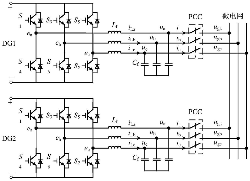
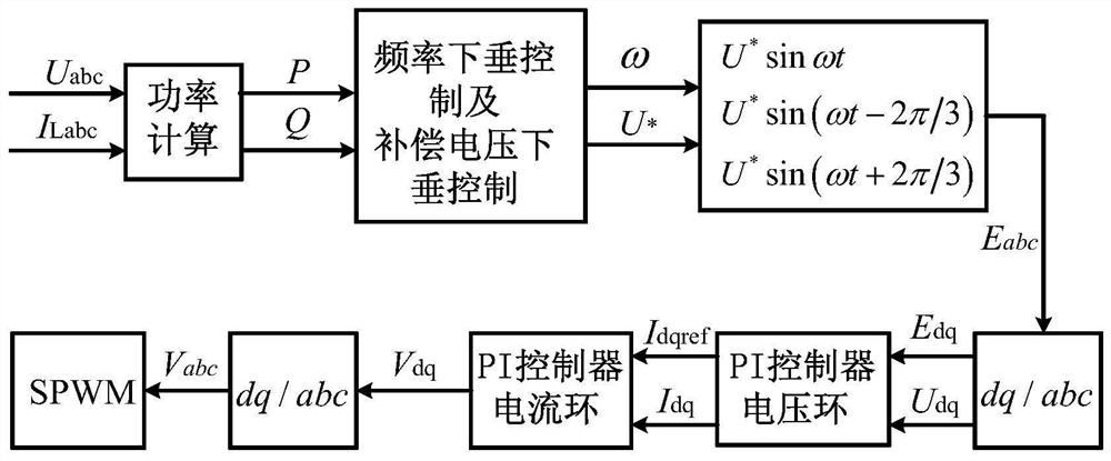
[0080] An improved method of improving the reactive power distribution of parallel inverters, combined figure 1 , figure 2 Specifically, follow the steps below:

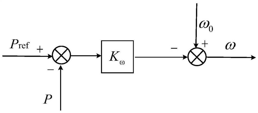
[0081] Step 1, calculate the output voltage U of the two inverters in the DQ coordinate system, respectively. d1 U q1 U d2 U q2 Output current I d1 I q1 I d2 I q2 , By active power P 1 , P 2 Calculate angular frequency Ω 1 Ω 2 Specifically, follow the steps below:

[0082] Step 1.1, two inverters are connected in parallel with load, set up two inverters DC bus voltage U dc 700V, filter resistor R f Inspiration L f , Capacitor C f They are: 0.01 Ω, 2MH, 50μF, line impedance, respectively, set to: z 1 = 1 + J2.56, Z 2 = 1.2 + J2.56, parallel load settings is: P = 6kw, q = 6kvar. Collect two inverters to output three-phase voltage U respectively a1 U b1 U c1 U a2 U b2 U c2 , Three-phase current I a1 I b1 I c1 I a2 I b2 I c2 ;

[0083] Step 1.2, calculate the active power P according to the two output three-phase voltage cur...


PUM


Abstract

The invention discloses a method for improving the reactive power distribution of parallel inverters. Firstly, the output voltage U of the two inverters in the dq coordinate system is respectively calculated. d1 , U q1 , U d2 , U q2 , output current I d1 , I q1 , I d2 , I q2 , by active power P 1 ,P 2 Calculate the angular frequency ω 1 , ω 2 ; Then use the reactive power-voltage droop control of the compensation voltage to calculate the reference voltage U of the output terminals of the two inverters 1 * , U 2 * ; Calculate the reference value E of the output voltage of the two inverters in the dq coordinate system d1 and E q1 ,E d2 and E q2 ; Finally, the PI controller is used as a voltage and current double closed-loop controller to control the voltage U of the two inverters in the dq axis coordinate system d1 , U q1 , voltage U d2 , U q2 , current I d1 , I q1 , current I d2 , I q2 control to obtain the PWM modulation signals of the two inverters, and realize the precise distribution of reactive power between the two inverters. Distribution deviation and parallel circulation problems.

Description

Technical field [0001] The present invention belongs to the field of power electronics, and is specifically related to improving the method of reactive power distribution of parallel inverters. Background technique [0002] The parallel micro-network inverter uses a sag control, and each distributed power supply DG is involved in the adjustment of the microgrid voltage and frequency. It automatically calculates the amount of change in the load system when the load is changed, and the load taken by each DG is The rated capacity is proportional to the proportion. However, the difference in equivalent line impedance causes the line impedance to mismatch, so that the reactive power cannot be accurately allocated and there is a circulation between the parallel inverters. [0003] In response to this problem, existing control methods have a virtual impedance and improve the sagging control. [0004] The effect of the virtual impedance is also different. First, by adding virtual impedan...

Claims


Application Information

Patent Timeline
Patent Type & Authority Patents(China)
IPC IPC(8): H02J3/50H02M7/493
CPCH02J3/50H02M7/493
Inventor 张辉张倩李晓强支娜梁誉馨
Owner XIAN UNIV OF TECH
Why Eureka
Try Eureka