Motorcycle with antilock brake system

a technology of anti-lock brakes and motorcycles, applied in the direction of jet propulsion mounting, cycle equipment, cycle brakes, etc., can solve the problems of difficult attachment and removal of the abs, difficulty in ensuring sufficient space for the abs-unit in view of body frame components, and significant design constraints on the front cowl. , to achieve the effect of effectively preventing vibration of the abs-unit, and reducing the number of vibrations

Active Publication Date: 2005-06-23
SUZUKI MOTOR CORP
View PDF9 Cites 75 Cited by
  • Summary
  • Abstract
  • Description
  • Claims
  • Application Information

AI Technical Summary

Benefits of technology

[0006] An object of the present invention is to substantially eliminate defects or drawbacks encountered in the prior art mentioned above and to provide a motorcycle provided with an antilock brake system capable of avoiding an expansion and design constraints of a front cowl associated with the installation of an ABS-unit, maintaining proper weight distribution between the front and rear of the vehicle body, providing improved brake performance and engine performance, allowing for easy attachment and removal of the ABS-unit while keeping an easy installation of brake pipes, and effectively preventing vibrations of the ABS-unit from being transmitted, with a simple structure.

Problems solved by technology

As a result, the front cowl suffers from considerable design constraints.
If the ABS-unit is arranged behind the head pipe in consideration of the matters mentioned above, it is difficult to secure sufficient space to accommodate the ABS-unit in view of body frame components.
This not only causes difficulties in attaching and removing the ABS-unit in a case of trouble or the like, but also causes difficulties in installing of general rubber brake hoses having large diameters.
However, use of small-diameter metal brake pipes causes further difficulties in attaching and removing the ABS-unit.
Moreover, vibrations of the ABS-unit during its operation cannot be fully absorbed only by the metal brake pipes and are transmitted to the body frame, thereby causing discomfort to the rider.

Method used


Image

  • Motorcycle with antilock brake system
  • Motorcycle with antilock brake system
  • Motorcycle with antilock brake system

Examples


Embodiment Construction

[0029] A preferred embodiment of the present invention will be described hereunder with reference to the accompanying drawings.

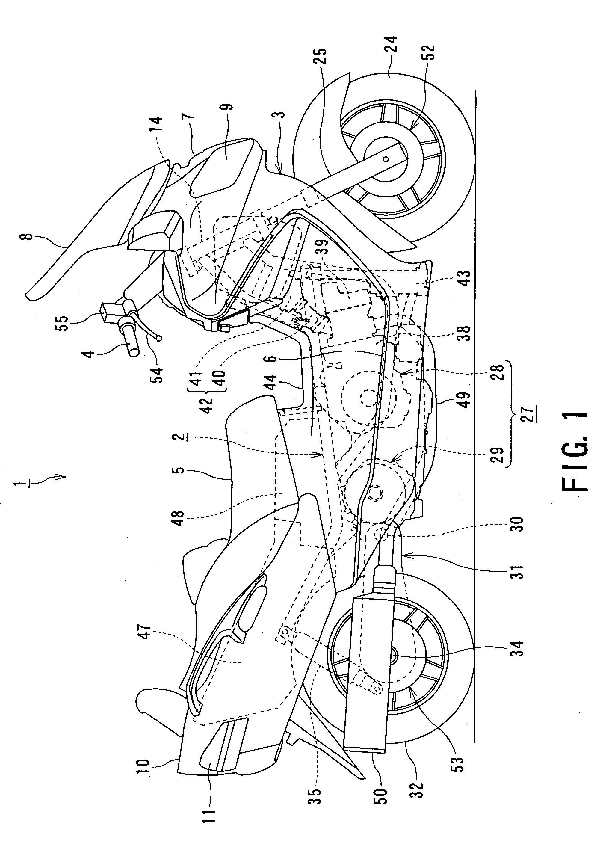
[0030] First, with reference to FIG. 1, a motorcycle 1 has a body frame 2 composed of steely pipes, which is covered with a resin frame cover 3. The motorcycle 1 is so-called scooter type one in which a portion between a handle-bar and a rider's seat is lowered to form a low-floored footrest 6.

[0031] The frame cover 3 forms a front cowl 7 covering the front end of the vehicle body. The front cowl 7 is provided, at an upper portion thereof, with a wind-shield 8 and, at a front end portion thereof, with a headlamp 9. The frame cover 3 forms a rear body 10 covering the rear portion of the vehicle (motorcycle) body and is provided with a tail lamp 11 at the tail portion.

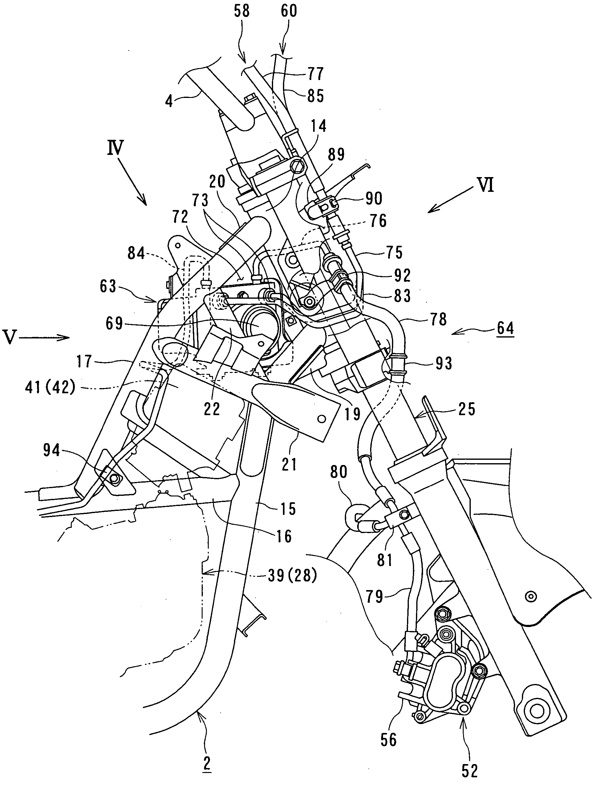
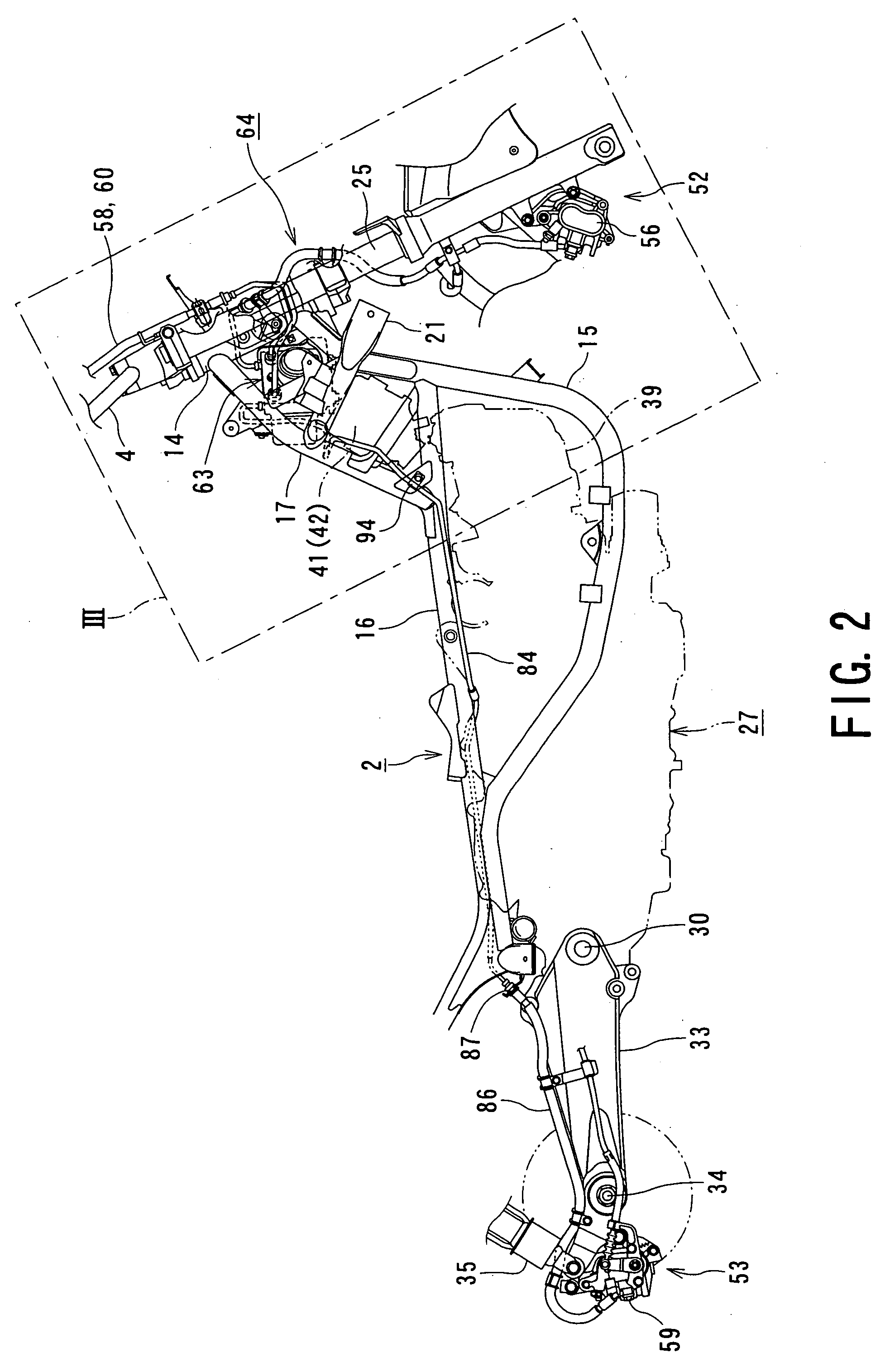
[0032] As shown in FIGS. 2 and 3, the body frame 2 includes a head pipe 14 at the front end. From the lower portion of the head pipe 14, a pair of left and right lower pipes 15 extends oblique...


PUM


Abstract

In a motorcycle provided with an antilock brake system, a front fork supporting a front wheel of a motorcycle is supported to be rotatable by a head pipe which is located at the front end portion of a body frame of a motorcycle, a handle-bar is secured to an upper end portion of the head pipe, master cylinders attached to the handle-bar are connected to hydraulic wheel brakes, respectively, via brake pipes. An antilock brake system includes an ABS-unit for antilock control disposed in an intermediate portion of the brake pipes. The ABS-unit is disposed immediately behind the head pipe and between a pair of body frame components disposed on both lateral sides of the motorcycle body and extending, from the head pipe, obliquely downward and backward, while extending outward in directions opposite to each other in the width direction of the motorcycle body.

Description

BACKGROUND OF THE INVENTION [0001] 1. Field of the Invention [0002] The present invention relates to a two-wheeled motor vehicle, such as motorcycle, provided with an antilock brake system, in which an ABS-unit is mounted on a vehicle body frame. [0003] 2. Related Art [0004] Hitherto, in a scooter-type two-wheeled motor vehicle, which may be called “motorcycle” hereunder, in which a low-floored footrest is provided between a handle-bar and a seat, an ABS-unit of an antilock brake system is normally located in the vicinity of a head pipe at the front end of a vehicle body frame, in particular, in front of the head pipe, such as disclosed in Japanese Unexamined Patent Laid-open Publication No. HEI 9-216547 and No. HEI 11-314589. This arrangement is determined in consideration of the weight distribution between the front and rear portions of the motorcycle, reduction of the length of brake pipes, and so on. However, in an arrangement in which the ABS-unit is arranged in front of the he...

Claims


Application Information

Patent Timeline
Patent Type & Authority Applications(United States)
IPC IPC(8): B60T8/34B60T8/36B62L3/00B62L3/02
CPCB62L3/023B60T8/3685
Inventor ASAHI, KOJI
Owner SUZUKI MOTOR CORP
Why Eureka
Try Eureka