Garden potted plant soil changing device

A garden and ring-shaped technology, which is applied in the field of potted soil replacement devices for gardens, can solve the problems of damage to potted plants, uneven strength, etc., and achieve the effect of uniform strength and convenient soil replacement

Active Publication Date: 2018-12-11
惠安权小白科技有限公司
View PDF12 Cites 4 Cited by
  • Summary
  • Abstract
  • Description
  • Claims
  • Application Information

AI Technical Summary

Problems solved by technology

[0003] In order to overcome the disadvantage that when ordinary people beat potted plants at present, due to the uneven

Method used


Image

  • Garden potted plant soil changing device
  • Garden potted plant soil changing device
  • Garden potted plant soil changing device

Examples


Embodiment 1

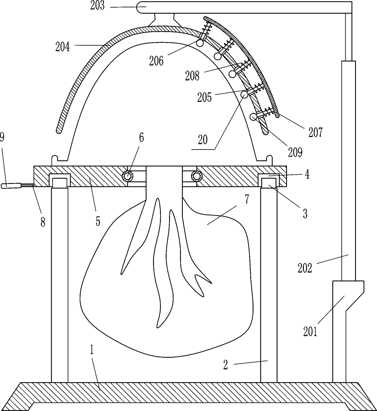
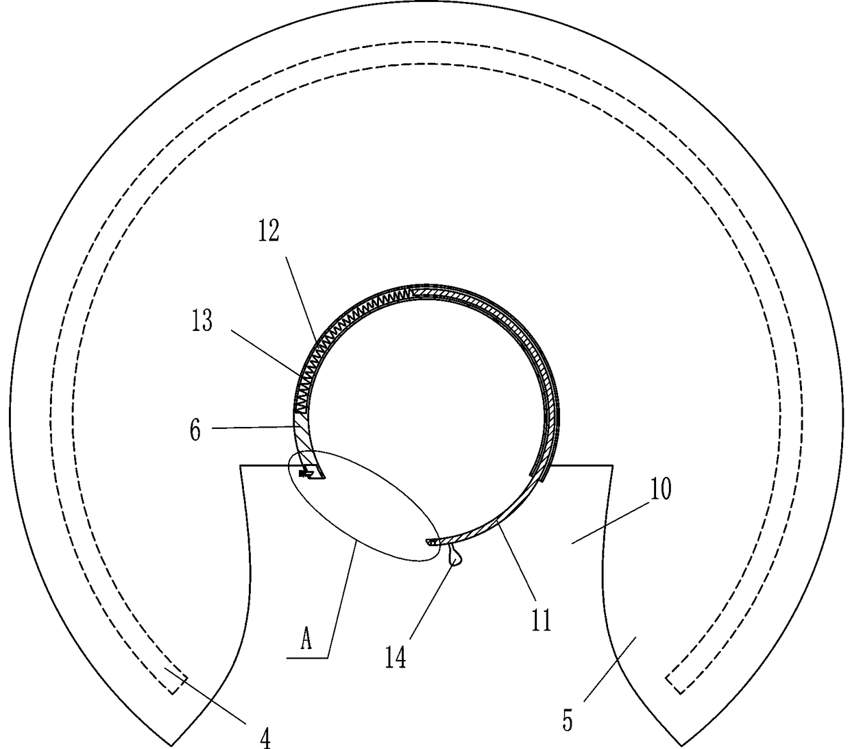
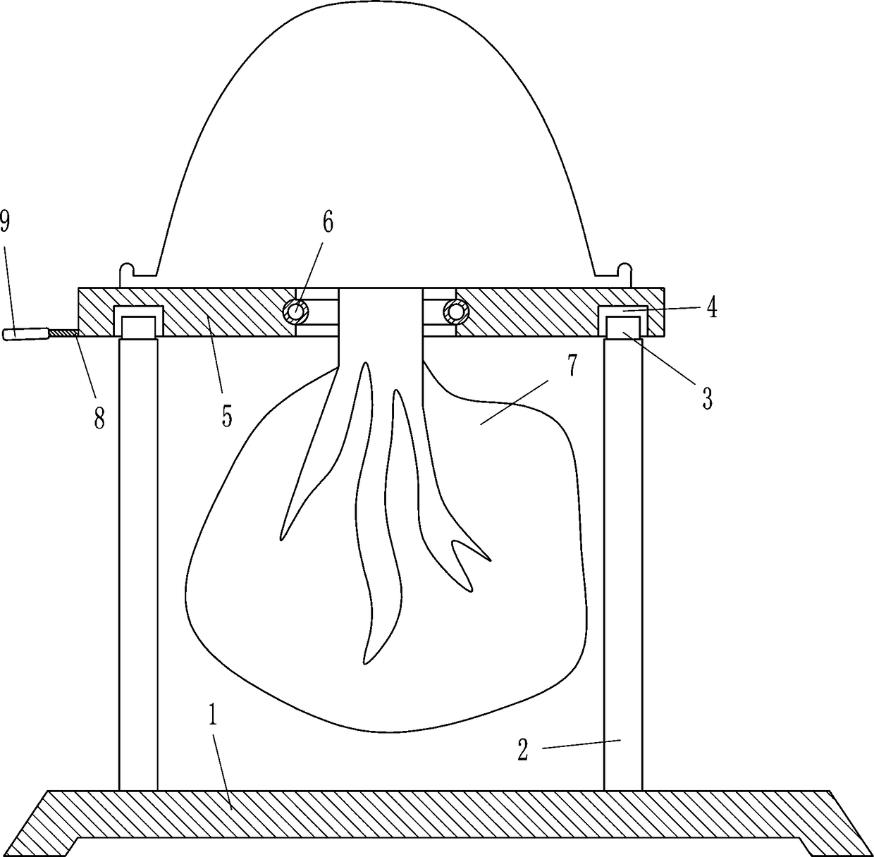
[0022] A potted plant soil replacement device for gardens, such as Figure 1-6 As shown, it includes a bottom plate 1, a pole 2, an annular slider 3, an annular plate 5, a semicircular plate 6, a fixed plate 8, a handle 9, an arc-shaped lever 11, a first spring 13, a pull block 14, Inserting rod 18 and second spring 19, bottom plate 1 top left and right sides are all equipped with support rod 2, and left and right sides support rod 2 tops are provided with ring plate 5, and ring plate 5 bottom is circumferentially provided with annular chute 4, and ring slide The groove 4 is provided with an annular slider 3, the annular slider 3 is slidingly matched with the annular chute 4, the bottom of the annular slider 3 is connected with the tops of the poles 2 on the left and right sides, and the left side of the outer side of the annular plate 5 is equipped with a fixed plate 8 , a handle 9 is installed on the left side of the fixed plate 8, an opening 10 is provided in the middle par...

Embodiment 2

[0024] A potted plant soil replacement device for gardens, such as Figure 1-6 As shown, it includes a bottom plate 1, a pole 2, an annular slider 3, an annular plate 5, a semicircular plate 6, a fixed plate 8, a handle 9, an arc-shaped lever 11, a first spring 13, a pull block 14, Inserting rod 18 and second spring 19, bottom plate 1 top left and right sides are all equipped with support rod 2, and left and right sides support rod 2 tops are provided with ring plate 5, and ring plate 5 bottom is circumferentially provided with annular chute 4, and ring slide The groove 4 is provided with an annular slider 3, the annular slider 3 is slidingly matched with the annular chute 4, the bottom of the annular slider 3 is connected with the tops of the poles 2 on the left and right sides, and the left side of the outer side of the annular plate 5 is equipped with a fixed plate 8 , a handle 9 is installed on the left side of the fixed plate 8, an opening 10 is provided in the middle par...

Embodiment 3

[0027] A potted plant soil replacement device for gardens, such as Figure 1-6 As shown, it includes a bottom plate 1, a pole 2, an annular slider 3, an annular plate 5, a semicircular plate 6, a fixed plate 8, a handle 9, an arc-shaped lever 11, a first spring 13, a pull block 14, Inserting rod 18 and second spring 19, bottom plate 1 top left and right sides are all equipped with support rod 2, and left and right sides support rod 2 tops are provided with ring plate 5, and ring plate 5 bottom is circumferentially provided with annular chute 4, and ring slide The groove 4 is provided with an annular slider 3, the annular slider 3 is slidingly matched with the annular chute 4, the bottom of the annular slider 3 is connected with the tops of the poles 2 on the left and right sides, and the left side of the outer side of the annular plate 5 is equipped with a fixed plate 8 , a handle 9 is installed on the left side of the fixed plate 8, an opening 10 is provided in the middle par...


PUM


Abstract

The invention relates to a soil changing device, in particular to a garden potted plant soil changing device and provides a garden potted plant soil changing device which is uniform in potted plant knocking force and capable of preventing influences on subsequent use due to potted plant damages. The technical scheme includes that the garden potted plant soil changing device comprises a bottom plate, supporting rods, an annular slider, a circular plate, semicircular plates, a fixing plate, a handle and the like. The supporting rods are mounted on left and right sides of the top of the bottom plate, the circular plate is arranged above the left and right supporting rods, the bottom of the circular plate is peripherally provided with an annular slide groove, and the annular slider is arrangedin the annular slide groove and is in slide fit with the annular slide groove. By a knocking device, uniformity in potted plant knocking force is achieved, and then soil in potted plants can be completely separated to make it convenient for subsequent soil changing. By action of a motor, manual knocking of the potted plants is avoided, so that time saving and labor saving are realized. By a clamping device, potted plant clamping and fixing can be realized, and influences of potted plant moving on ball knocking are prevented.

Description

technical field [0001] The invention relates to a soil replacement device, in particular to a garden potted soil replacement device. Background technique [0002] In the garden, a large number of potted plants are usually placed for people to watch. At the same time, the surrounding environment can be purified to make the surrounding environment better. When the potted plants are placed for a long time, they need to be replaced regularly. For potted plants, it is necessary to beat the potted plants to separate the soil from the potted plants. At present, when ordinary people beat the potted plants, due to the uneven force, it is easy to damage the potted plants and affect the subsequent use, and use a shovel to loosen the soil and separate from the potted plants, which is easy to damage the inside of the potted plants. Plant damage, and even affect the subsequent normal growth of plants. Contents of the invention [0003] In order to overcome the disadvantage that when or...

Claims


Application Information

Patent Timeline
IPC IPC(8): A01G9/08
CPCA01G9/086
Inventor 戴锐城
Owner 惠安权小白科技有限公司
Why Eureka
Try Eureka