
A belting machine for umbrellas

A technology for straps and umbrellas, applied in the direction of walking sticks, etc., can solve the problems of slippery ground, messy ground, affecting the hygiene of public places, etc., and achieve the effect of simple operation.

Active Publication Date: 2020-10-13
戚明海
View PDF10 Cites 0 Cited by
  • Summary
  • Abstract
  • Description
  • Claims
  • Application Information

AI Technical Summary

Problems solved by technology

[0003] Aiming at the deficiencies of the prior art, the present invention provides an umbrella strapping machine, which has the advantages of bagging the umbrella, preventing raindrops from splashing on the ground, and avoiding the slipping of personnel due to the wet and slippery ground. Bring the umbrella directly into the public place, and the raindrops will splash on the ground, which will cause the ground to be slippery, which will easily cause people to slip and fall. At the same time, the rain will cause the ground to be messy and affect the sanitation of public places.

Method used


Image

  • A belting machine for umbrellas
  • A belting machine for umbrellas
  • A belting machine for umbrellas

Examples


Embodiment 1

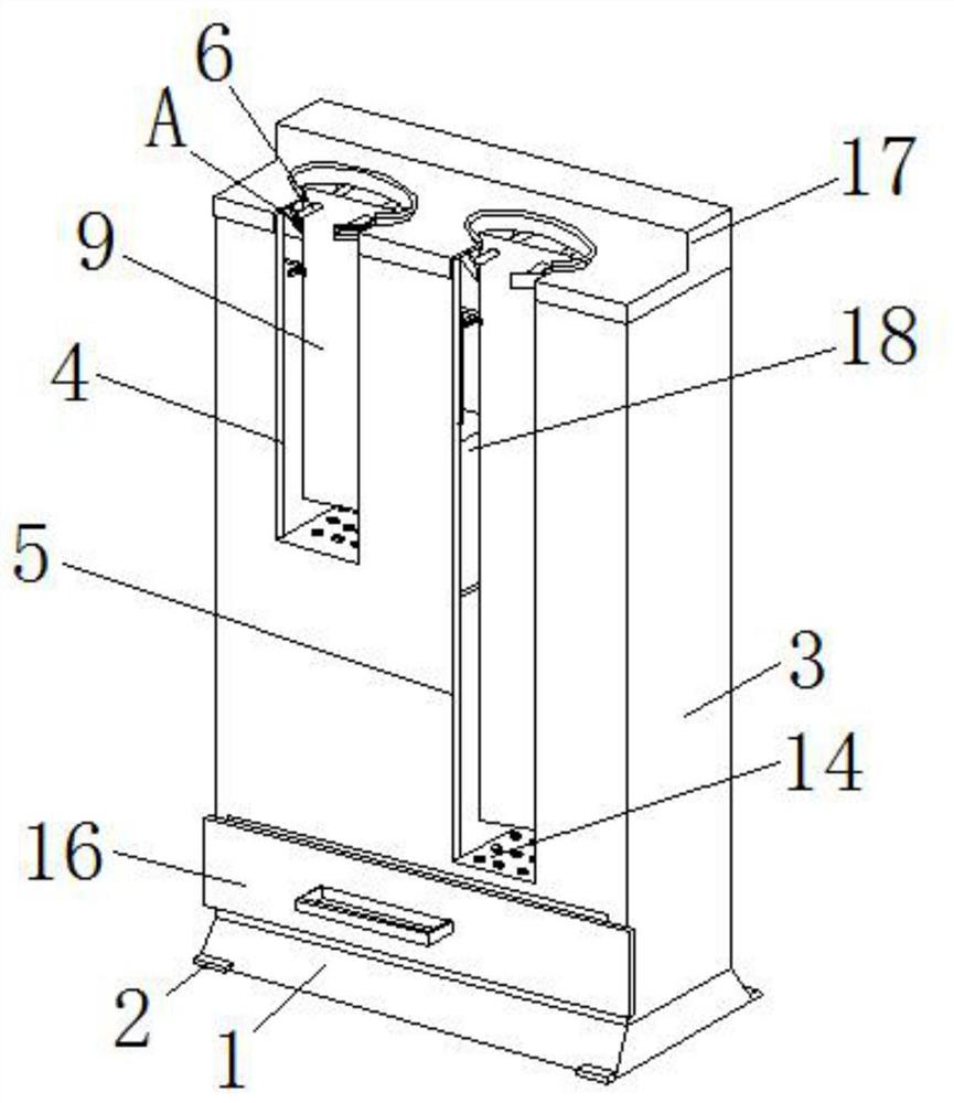
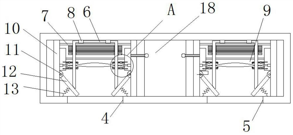
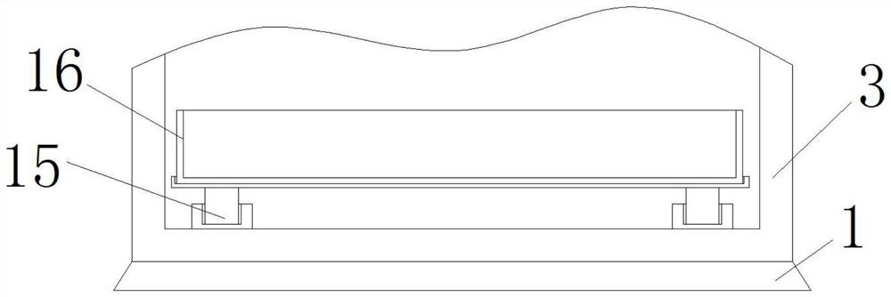
[0021] see Figure 1-4 , the present embodiment provides an umbrella belting machine, comprising a base 1, the top of the base 1 is fixedly connected with a bagging box 3, the front of the bagging box 3 is provided with a first umbrella opening 4, and the front of the bagging box 3 Offer the second umbrella port 5 that is positioned at the first umbrella port 4 side, the inwall of bagging box 3 rotates and has bagging support 6, and the inwall of bagging box 3 is fixedly connected with strut 7, and strut 7 is connected with sleeve. The bag support 6 is movably connected, the surface of the bag support 6 is sleeved with an umbrella bag 9, the inner wall of the bag box 3 is fixedly connected with a mounting plate 10, and one side of the mounting plate 10 is fixedly connected with a hinged seat 11, one of the hinged seats 11 The side is hinged with a stopper 12, the stopper 12 is movably connected with the bagging support 6, and one side of the mounting plate 10 is fixedly connec...

Embodiment 2

[0024] see Figure 1-3 , on the basis of Example 1, a further improvement is made: the base 1 is a truss type, and both sides of the base 1 are fixedly connected with rubber blocks 2, and setting the base 1 into a prism shape can effectively increase the distance between the base 1 and the ground. The contact area, combined with the supporting effect of the rubber block 2, can make the overall stability of the device higher, making it difficult to dump during the bagging process. The first umbrella opening 4 is the small umbrella bag picking area, and the second umbrella picking Umbrella port 5 is a bag-taking area for a large umbrella, and the height of the first umbrella port 4 is less than the height of the second umbrella port 5, so that the device can bag umbrellas of different lengths, increasing the applicability of the device. The inner wall of the bagging box 3 is fixedly connected with a hinge 8, and the hinge 8 is hinged with the bagging support 6. When the umbrella...


PUM


Abstract

The invention relates to the technical field of umbrellas, and discloses an umbrella bagging machine, including a base. A bagging box is fixedly connected to the top of the base; the front of the bagging box is provided with the first umbrella-taking opening and the second umbrella-taking opening on one side of the first opening; the inner wall of the bagging box rotates with a bagging bracket; astrut is fixed to the inner wall of the bagging box; the strut is movably connected to the bagging bracket; the surface of the bagging bracket is sleeved with an umbrella bag; an installation plate is fixed to the inner wall of the bagging box; an articulated seat is fixed to one side of the installation plate; one side of the articulated seat is articulated with a block that is movably connectedto the bagging bracket. The invention solves the problem that umbrellas are directly brought into a public place and raindrops splash on the ground, causing the ground to be wet and slippery, which is inclined to cause people to slip and the like. At the same time, rainwater will cause the ground to be messy and affect the sanitation of public places.

Description

technical field [0001] The invention relates to the technical field of umbrellas, in particular to an umbrella strapping machine. Background technique [0002] In rainy and snowy weather, umbrellas are necessary equipment for people to go out. When people carry umbrellas into some public places such as shopping malls, because the surface of the umbrella will occupy a large amount of rainwater, these raindrops will splash on the ground, which will cause the ground to be slippery. , It is easy to cause phenomena such as personnel slipping, and rainwater will cause the ground to be messy at the same time, affecting the sanitation of public places. An umbrella bagging machine is now proposed to solve the above problems. Contents of the invention [0003] Aiming at the deficiencies of the prior art, the present invention provides an umbrella strapping machine, which has the advantages of bagging the umbrella, preventing raindrops from splashing on the ground, and avoiding the s...

Claims


Application Information

Patent Timeline
Patent Type & Authority Patents(China)
IPC IPC(8): A45B25/24A45B25/28
CPCA45B25/24A45B25/28
Inventor 吴银霞
Owner 戚明海
Learn More