Rotation sprayer structure for paint spraying robot

A technology of rotating nozzles and robots, applied in the direction of spraying devices, etc., can solve the problems of small spraying range and poor use effect, and achieve the effect of expanding the spraying range

Inactive Publication Date: 2018-12-11
WUHU CITY YUEZE ROBOT TECH CO LTD
View PDF0 Cites 4 Cited by
  • Summary
  • Abstract
  • Description
  • Claims
  • Application Information

AI Technical Summary

Problems solved by technology

[0002] Existing nozzle structures for painting robots are usually only capable of

Method used


Image

  • Rotation sprayer structure for paint spraying robot
  • Rotation sprayer structure for paint spraying robot

Examples


Example Embodiment

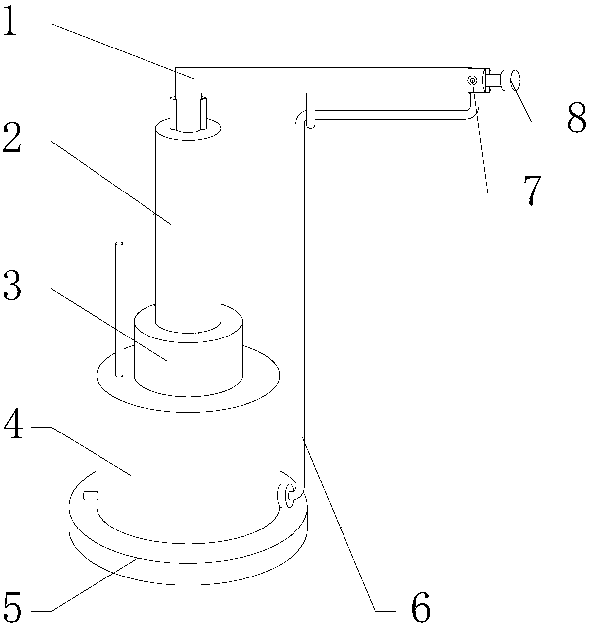
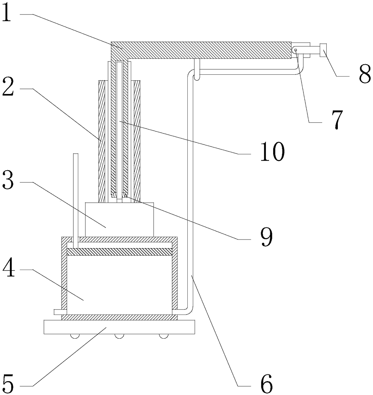
[0019] Specific implementation method: in actual use, the user holds the rotating rod 7 and rotates counterclockwise, and the rotating rod 7 rotates to drive the nozzle 8 to rotate, so as to realize the nozzle 8 facing upwards. If the rotating rod 7 is rotated counterclockwise, then Realize the downward rotation of the nozzle 8. When the nozzle 8 rotates to the designated direction, the user holds the rotation rod 7 and the nut respectively, and rotates the nut, and then the nut rotates and moves inward, thereby the L-shaped telescopic rod 1 The top is tightened to fix the rotating rod 7, and then the user opens the switch connecting the motor 3 and the external power supply to realize the circuit connection between the motor 3 and the external power supply, and then the motor 3 works to drive the screw rod 10 to rotate, and then the screw rod 10 rotates to drive the nut seat 9 to move upward along the screw rod 10, and the upward movement of the nut seat 9 drives the L-shaped ...


PUM


Abstract

The invention provides a rotation sprayer structure for a paint spraying robot. The rotation sprayer structure comprises an L-shaped telescopic rod, a fixing pipe, a motor, a paint spraying tank, a connecting hose, a rotation rod, a sprayer, a nut base and a lead screw. The L-shaped telescopic rod is arranged on the upper end face of the fixing pipe in a sliding manner. The fixing pipe is fixed tothe upper end of the motor. The motor is fixed to the upper end face of the paint spraying tank through a flange plate. The connecting hose is connected to the lower right portion of the annular sideface of the paint spraying tank. The upper end of the connecting hose is connected to the lower end of the sprayer. The left end of the sprayer is connected with the L-shaped telescopic rod through the rotation rod. The lead screw is fixed to an output shaft on the upper side of the motor. The nut base is arranged on the annular side face of the lead screw through a ball nut pair, and the nut base is embedded in the lower end of the L-shaped telescopic rod. Through the design, the paint spraying range is enlarged. The rotation sprayer structure is convenient to use and operate, the paint spraying range is enlarged, and the lifting function is achieved.

Description

technical field [0001] The invention relates to a rotary nozzle structure for a painting robot, which belongs to the field of robot accessory equipment. Background technique [0002] The existing nozzle structure for painting robots can usually only spray paint in one direction, the spraying range is small, and the use effect is poor. Contents of the invention [0003] Aiming at the deficiencies in the prior art, the object of the present invention is to provide a rotary spray head structure for a painting robot to solve the problems raised in the above-mentioned background technology. The present invention is easy to use, easy to operate, expands the scope of painting, and realizes lifting Function. [0004] In order to achieve the above object, the present invention is achieved through the following technical solutions: a rotating nozzle structure for a painting robot, including an L-shaped telescopic rod, a fixed pipe, a motor, a paint spray tank, a base, a connecting ...

Claims


Application Information

Patent Timeline
IPC IPC(8): B05B13/04B05B15/628
CPCB05B13/0421B05B15/628
Inventor 黄浩吴丹阳
Owner WUHU CITY YUEZE ROBOT TECH CO LTD
Why Eureka
Try Eureka