Air shower

A technology of air shower and main body, which is applied in the field of air shower, and can solve the problems of blocking the air flow path, and achieve the effect of improving dust removal efficiency, improving dust removal effect, diversifying air flow direction and air flow path

Pending Publication Date: 2018-12-11
HUBEI UNIV OF SCI & TECH
View PDF1 Cites 2 Cited by
  • Summary
  • Abstract
  • Description
  • Claims
  • Application Information

AI Technical Summary

Problems solved by technology

[0010] The purpose of the present invention is to provide an air shower for the above problems existing in the existing technology. The technical problem to be solved by the present invention is how to improve the dust removal efficiency and prevent dust from blocking the air flow path.

Method used


Image

  • Air shower
  • Air shower
  • Air shower

Examples


Embodiment Construction

[0033] The following are specific embodiments of the present invention and in conjunction with the accompanying drawings, the technical solutions of the present invention are further described, but the present invention is not limited to these embodiments.

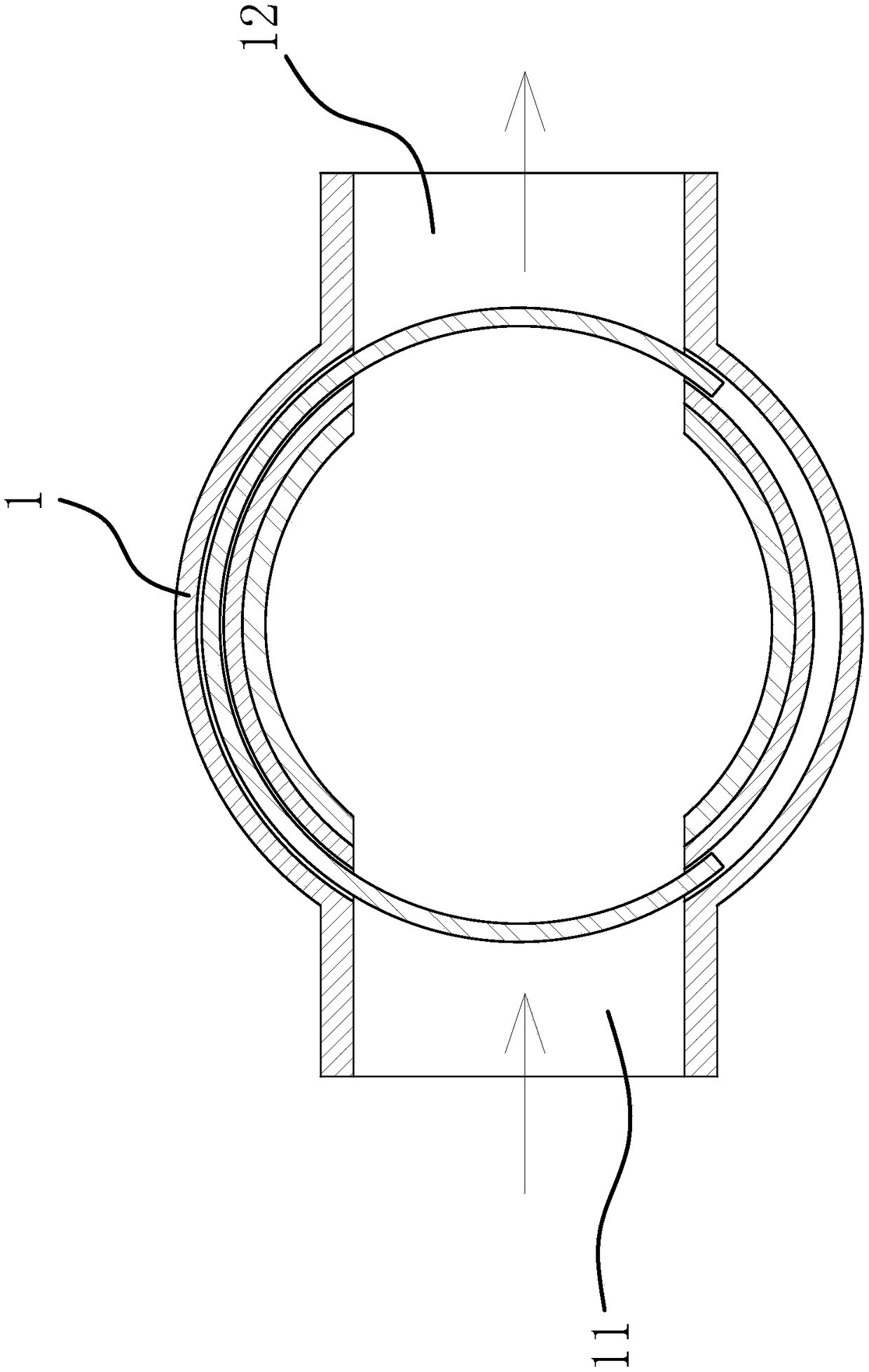
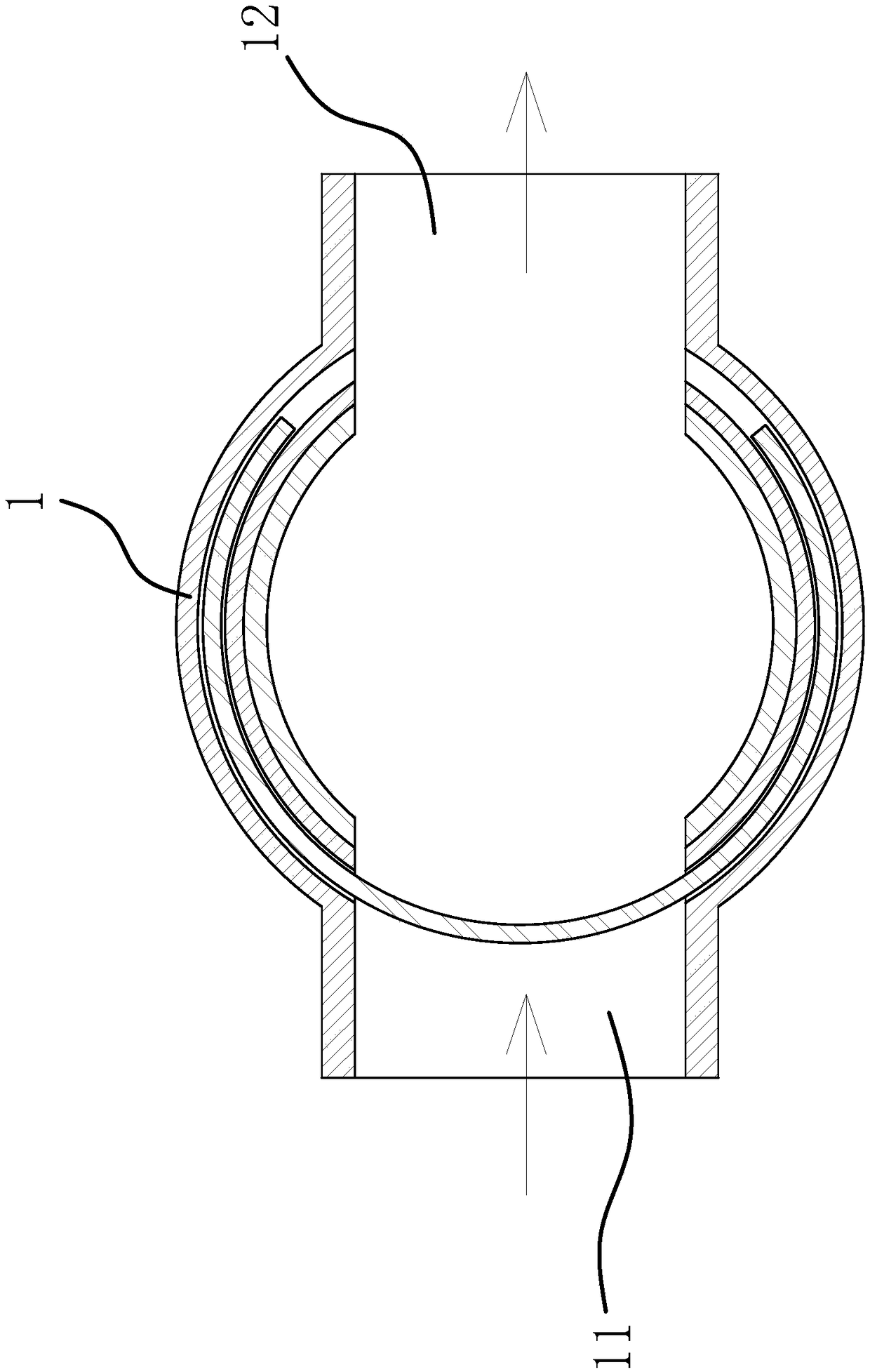
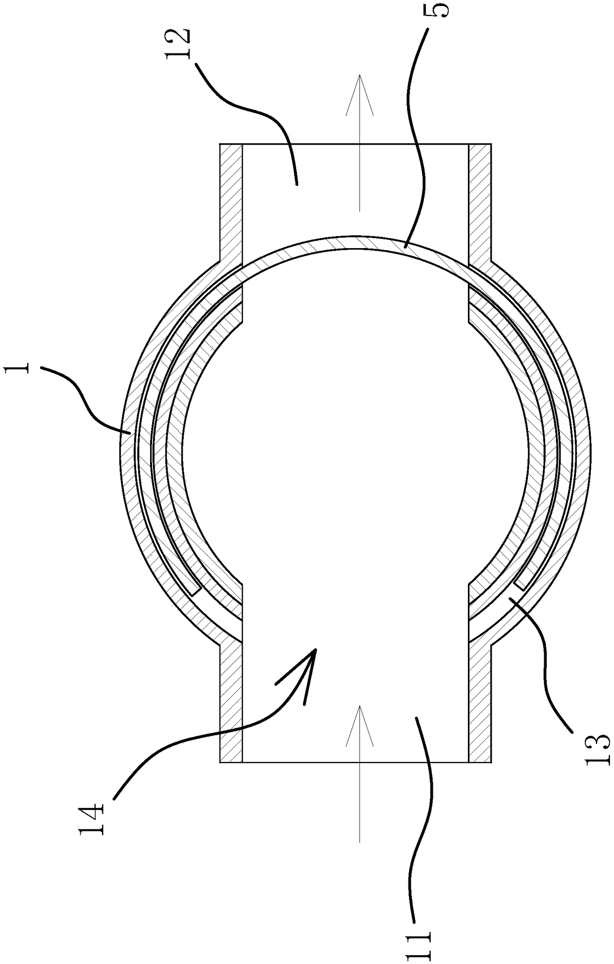
[0034] Such as figure 1 , figure 2 , image 3 , Figure 4 and Figure 6 As shown, the air shower room includes a main body 1, an entrance corridor 11 and an exit corridor 12. The entrance of the main body 1 communicates with the entrance corridor 11, and the exit of the main body 1 communicates with the exit corridor 12. The entrance and exit of the door body 5;

[0035] The air shower room also includes a blower 2, a stepping motor 41, a vacuum cleaner 3 and a valve body 42. The body 1 is provided with a number of air nozzles 43, and the valve body 42 is rotatably connected with a rotary valve 44. The rotary valve 44 is connected to the stepping motor. The output shafts of 41 are fixedly connected, the housing of th...


PUM

PropertyMeasurementUnit
Radianaaaaaaaaaa

Abstract

The invention provides an air shower and belongs to the technical field of dedusting equipment. The air shower comprises a body, an inlet corridor and an outlet corridor, wherein an inlet of the bodycommunicates with the inlet corridor, and an outlet of the body communicates with the outlet corridor. The air shower also comprises a blower, a stepping motor, a dust collector and a valve body. Thebody is provided with a plurality of gas nozzles. A rotating valve is rotatably connected to the valve body and fixedly connected with an output shaft of the stepping motor. A casing of the stepping motor is fixed to the valve body. The rotating valve is longitudinally provided with vent holes in one-to-one correspondence to the gas nozzles. The valve body is provided with a gas inlet cavity and agas suction cavity, wherein the gas inlet cavity is connected with a gas outlet end of the blower, and the gas suction cavity is connected with a gas suction end of the dust collector. During the rotation of the rotating valve, the vent holes can intermittently communicate with the gas suction cavity or the gas inlet cavity; each gas nozzle is connected with the corresponding gas nozzle through ahose. The air shower has the advantage of being capable of improving the dedusting efficiency.

Description

technical field [0001] The invention belongs to the technical field of dust removal equipment and relates to an air shower room. Background technique [0002] In the field of air purification, an air shower is generally installed between the clean area and the unclean area to clean the surface of people or goods. [0003] Compared with the Chinese patent application number 201721036179.1, an air shower room is disclosed, which includes an inner wall of the air shower and an outer wall of the air shower. A fan is arranged on the top of the outer wall of the air shower, and a fan is set between the fan and the inner wall of the air shower. There is an air purifier, deflectors are arranged on both sides of the air purifier, an air duct is formed between the inner wall of the air shower and the outer wall of the air shower, and several nozzles are arranged on the inner wall of the air shower, close to the There is a voice-activated switch at the bottom of the air duct. [0004...

Claims


Application Information

Patent Timeline
IPC IPC(8): B08B5/02B08B13/00
CPCB08B5/02B08B13/00
Inventor 陈生安镇方雄镇依婷周志明吴俊智阮朝华锐王波
Owner HUBEI UNIV OF SCI & TECH
Why Eureka
Try Eureka