Industrial robot positioning and measuring device

An industrial robot, positioning measurement technology, applied in the direction of manipulators, manufacturing tools, etc., can solve the problems of inaccurate repeated positioning accuracy, cumbersome operation, waste of resources, etc., to reduce equipment and labor costs, simple operation, and improve accuracy Effect

Inactive Publication Date: 2018-12-11
安徽省勤业科技服务有限公司
View PDF5 Cites 0 Cited by
  • Summary
  • Abstract
  • Description
  • Claims
  • Application Information

AI Technical Summary

Problems solved by technology

In the process of measuring the repetitive positioning accuracy of industrial robots, the laser tracker must limit the speed of the robot within a certain range, otherwise there will be light loss and re-measurement is required. The repetitive positioning accuracy obtained under slow measurement is not accurate. , and this device has certain requirements for the operator, and the operation is cumbersome and the cost is extremely high. If it is only used for the measurement of the positioning accuracy of industrial robots, it will cause waste of resources, and in the process of finished product inspection of industrial robots, it is impossible to Each station is equipped with a laser tracker to detect industrial robots, so it is very necessary to invent a low-cost, easy-to-operate industrial robot positioning measurement device

Method used


Image

  • Industrial robot positioning and measuring device
  • Industrial robot positioning and measuring device
  • Industrial robot positioning and measuring device

Examples


Embodiment Construction

[0023] The following will clearly and completely describe the technical solutions in the embodiments of the present invention with reference to the accompanying drawings in the embodiments of the present invention. Obviously, the described embodiments are only some, not all, embodiments of the present invention. All other embodiments obtained by persons of ordinary skill in the art based on the embodiments of the present invention belong to the protection scope of the present invention.

[0024] According to an embodiment of the present invention, an industrial robot positioning measurement device is provided.

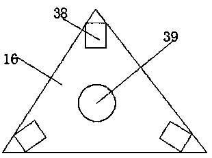
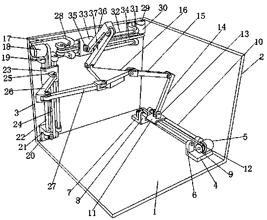
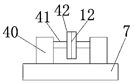
[0025] like Figure 1-3As shown, an industrial robot positioning measurement device according to an embodiment of the present invention includes a fixed plate one 1, and one side of the upper end of the fixed plate one 1 is provided with a fixed plate two 2, and the other upper end of the fixed plate one 1 is The side is provided with a fixed plate three 3, and the fi...


PUM


Abstract

The invention discloses an industrial robot positioning and measuring device. The industrial robot positioning and measuring device comprises a first fixing plate. One side of the upper end of the first fixing plate is provided with a second fixing plate. The other side of the upper end of the first fixing plate is provided with a third fixing plate. The first fixing plate, the second fixing plateand the third fixing plate are perpendicular mutually. The upper end of one side, adjacent to the second fixing plate, of the first fixing plate is provided with a first fixing base. One side of theupper end of the first fixing base is provided with a first motor. The other side of the upper end of the first fixing base is provided with two groups of first limiting blocks. The upper end, positioned at one side of the first fixing base, of the first fixing plate is provided with a second fixing base. One side, adjacent to the first fixing base, of the second fixing base is provided with two groups of second limiting blocks. The other side of the second fixing base is provided with a first connecting device. Two groups of first sliding rods are alternately installed between the first limiting blocks and the second limiting blocks. The two groups of the first sliding rods are provided with a first sliding plate. The lower end, positioned between the first motor and the first connectingdevice, of the first sliding plate is provided with a first conveying belt. The upper end of the first sliding plate is provided with a first connecting block.

Description

technical field [0001] The invention relates to the field of industrial robots, in particular to an industrial robot positioning and measuring device. Background technique [0002] At present, the precise positioning of industrial robots is mostly measured by laser trackers. In the process of measuring the repetitive positioning accuracy of industrial robots, the laser tracker must limit the speed of the robot within a certain range, otherwise there will be light loss and re-measurement is required. The repetitive positioning accuracy obtained under slow measurement is not accurate. , and this device has certain requirements for the operator, and the operation is cumbersome and the cost is extremely high. If it is only used for the measurement of the positioning accuracy of industrial robots, it will cause waste of resources, and in the process of finished product inspection of industrial robots, it is impossible to Each station is equipped with a laser tracker to detect ...

Claims


Application Information

Patent Timeline
Patent Type & Authority Applications(China)
IPC IPC(8): B25J19/00
CPCB25J19/0095
Inventor 刘亦奇
Owner 安徽省勤业科技服务有限公司
Why Eureka
Try Eureka