
Ink fountain

A technology of ink fountain and middleware, which is applied in the direction of printing, printing machines, general parts of printing machinery, etc., can solve the problems of reduced clamping force and difficult cleaning of clamping slats, and achieve the effect of reducing clamping force and avoiding

Active Publication Date: 2018-12-11
HEIDELBERGER DRUCKMASCHINEN AG
View PDF11 Cites 0 Cited by
  • Summary
  • Abstract
  • Description
  • Claims
  • Application Information

AI Technical Summary

Problems solved by technology

It is pointed out here that, in contrast to the case where the clamping strip is formed as an aluminum drawn part, when the clamping strip is formed as a bent part from elastic sheet metal, there is no risk that the clamping strip Deforms in an irreversible manner over time due to load
This irreversible deformation additionally leads to a reduction in the clamping force
[0003] A disadvantage of the prior art is that the clamping strips are difficult to clean due to their comb-like contours

Method used


Image

  • Ink fountain
  • Ink fountain
  • Ink fountain

Examples


Embodiment Construction

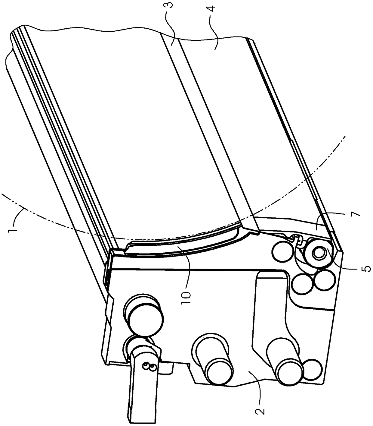
[0016] figure 1 Shows the components of the anilox inking mechanism of a printing press for offset printing. Shown is an anilox roller 1 and an ink fountain 2 with a doctor blade 3 which rests against the anilox roller 1 . The anilox roller 1 is only indicated by phantom lines and only a part of the ink fountain 2 is shown. A clamping strip 4 extends parallel to the scraper 3 for clamping the scraper 3 on the ink fountain. The clamping strip 4 is configured as a rocker and is actuated during clamping by means of an eccentric shaft 5 . One lever arm of the clamping strip 4 bears against the eccentric shaft 5 , while the other lever arm presses against the scraper 3 .

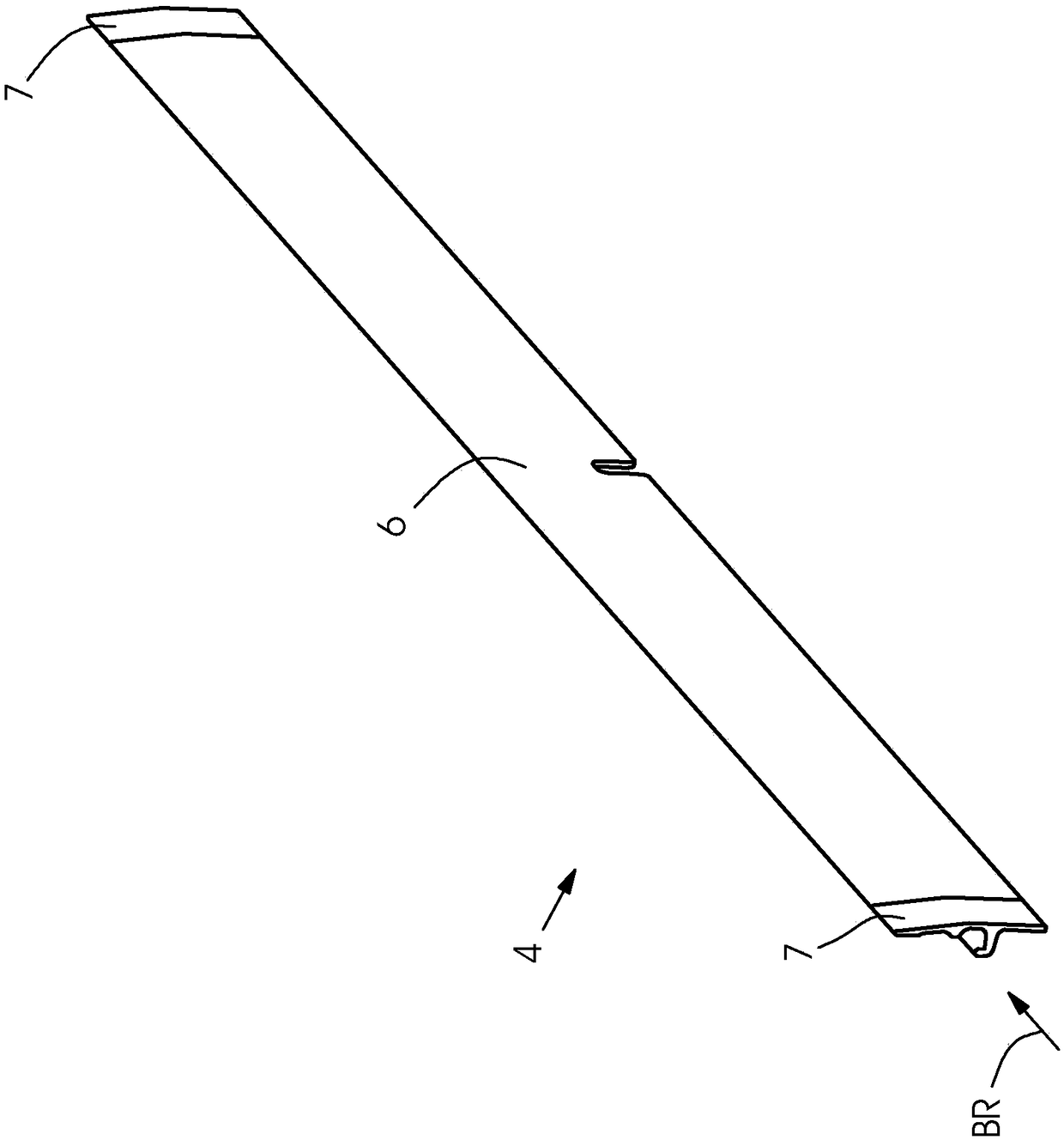
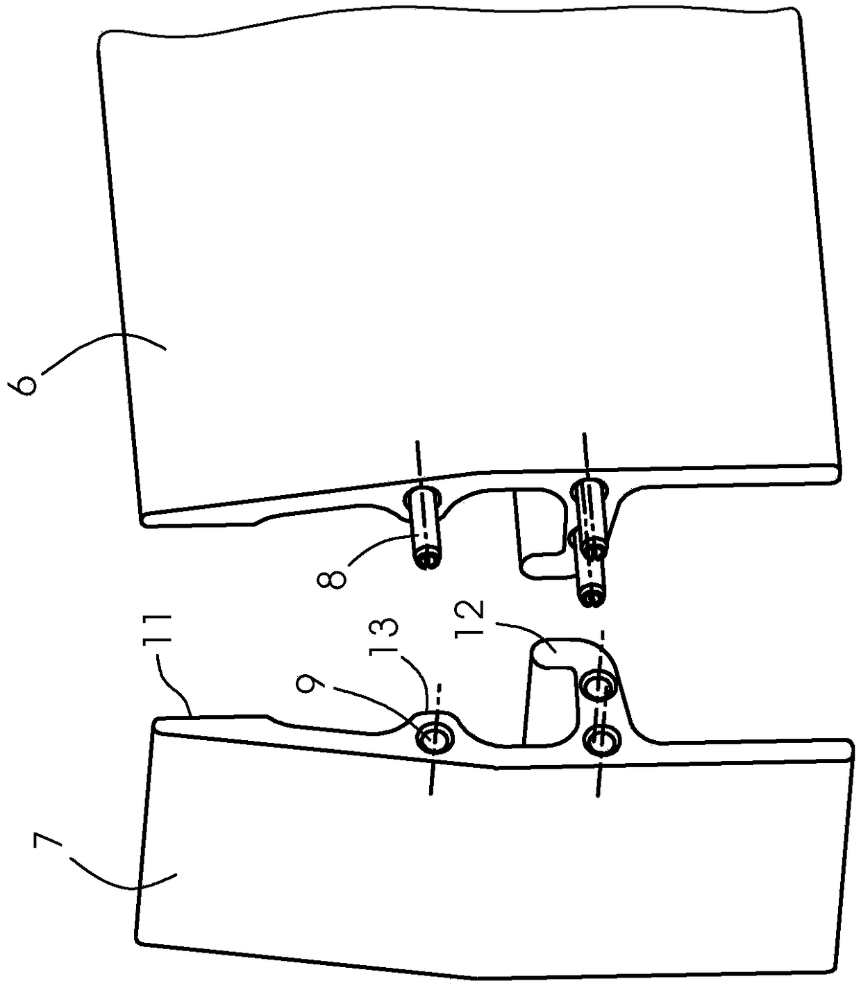
[0017] figure 2 It is shown that the clamping strip 4 comprises two end pieces 7 and a middle piece 6 located between them. The intermediate part 6 is arranged between the two end parts 7 parallel to the axis of rotation of the anilox roll 1 (as viewed according to the viewing direction BR). These end piec...


PUM


Abstract

An ink fountain of a printing press comprises a doctor blade and a clamping strip (4) for clamping the doctor blade. The clamping strip (4) is composed of a central piece (6) and end pieces (7).

Description

technical field [0001] The invention relates to an ink fountain of a printing machine, which includes a scraper and a clamping strip for clamping the scraper. Background technique [0002] Such an ink fountain is described in document DE 10 2015 207 719 A1. In ink fountains of this type from the prior art, the clamping bar is produced in a single piece as a comb-shaped curved plate part. The clamping slats include a set of lever arms that form an array. The lever arms at the ends of the array are configured wider than the remaining lever arms of the array. This segmentation is coordinated with the side wall seals of the storage container. The clamping slats can be made of elastic sheet metal. It is pointed out here that, in contrast to the case where the clamping strip is formed as an aluminum drawn part, when the clamping strip is formed as a bent part from elastic sheet metal, there is no risk that the clamping strip Deforms over time in an irreversible manner due to ...

Claims


Application Information

Patent Timeline
IPC IPC(8): B41F31/02B41F31/10B41F31/05
CPCB41F31/02B41F31/05B41F31/10B41F31/04B41F31/06
Inventor M·迪瓦斯
Owner HEIDELBERGER DRUCKMASCHINEN AG
Learn More