
A conveying device for furniture production

A technology for handling devices and furniture, applied in the direction of transportation and packaging, multi-axis trolleys, trolley accessories, etc., can solve problems such as unfavorable work, furniture slipping, inconvenient processing, etc., and achieve enhanced shock absorption, reduced bumps, and enhanced stability sexual effect

Inactive Publication Date: 2018-12-11
邓文
View PDF0 Cites 1 Cited by
  • Summary
  • Abstract
  • Description
  • Claims
  • Application Information

AI Technical Summary

Problems solved by technology

[0002] Furniture refers to the categories of utensils and facilities necessary for human beings to maintain normal life, engage in production practice and carry out social activities. Compared with large furniture, in recent years, in order to adapt to changes in market demand and people's life philosophy, smaller furniture Small-sized furniture is becoming more and more popular in the market. Many well-known furniture brands that have been focusing on selling standard-sized furniture have also begun to extend their business tentacles to small-sized furniture, whether it is larger or smaller. In the process, it is inconvenient to move and thus inconvenient to process, so a furniture handling device for furniture production is needed
[0003] However, there are still some deficiencies in the use of some existing furniture handling devices. During the use of the handling device, the furniture will slip due to the bumps on the ground during the process of moving the furniture, and the furniture needs to be lifted. On the handling device, and in the process of moving the furniture to the handling device, the handling device is prone to slippage, which is not conducive to work, very inconvenient, time-consuming and laborious, and needs to be improved

Method used


Image

  • A conveying device for furniture production
  • A conveying device for furniture production
  • A conveying device for furniture production

Examples


Embodiment 1

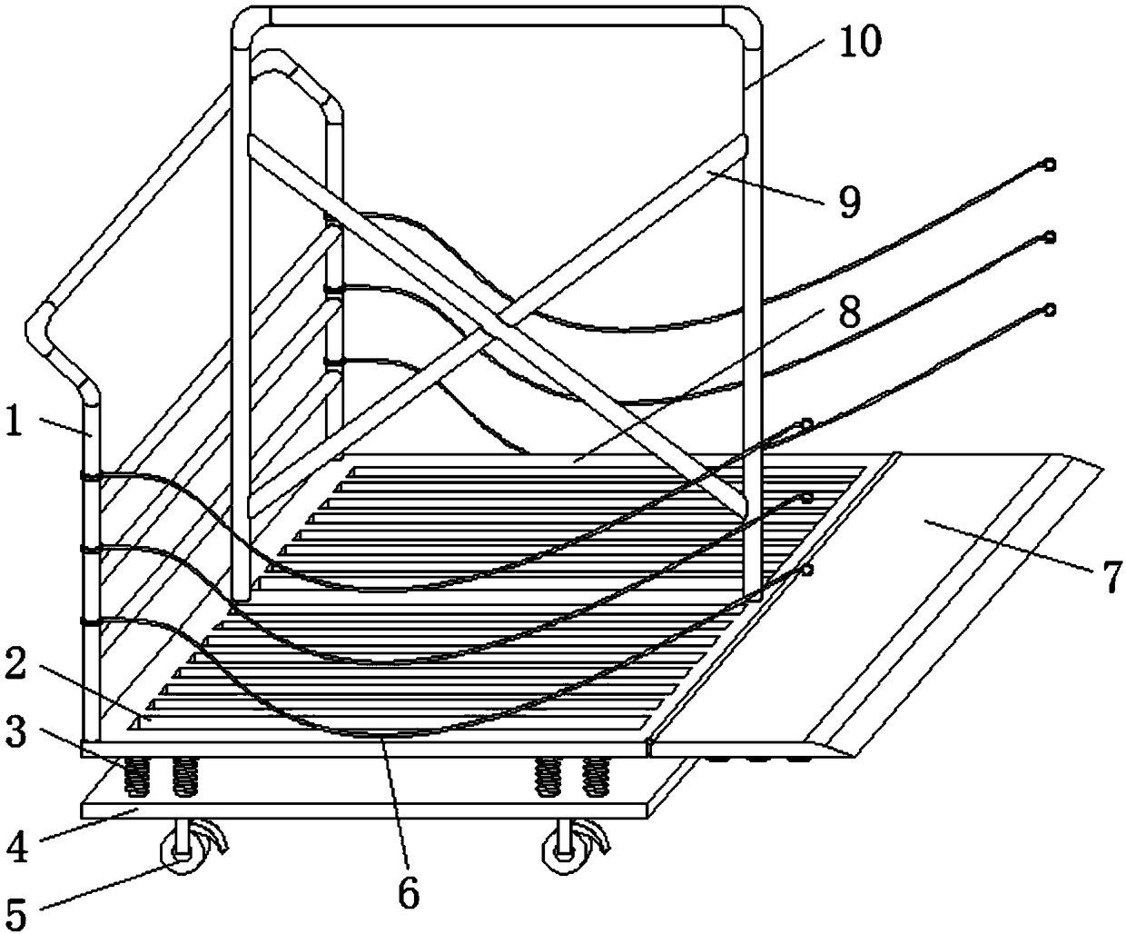
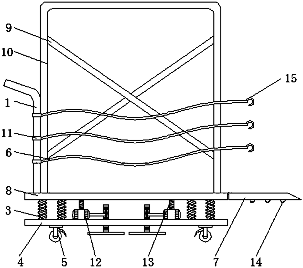
[0023] Embodiment one, with reference to Figure 1-2 , a carrying device for furniture production, comprising a carrying device body 8, a connecting rod 10 is welded at the top horizontal midline position of the carrying device body 8, a spacer 9 is welded inside the connecting rod 10, and the top side of the carrying device body 8 The push handle 1 is welded, the top of the handling device body 8 is equidistantly provided with a plurality of rectangular through holes 2, the spacer bar 9 has a cross-shaped structure, and the connecting rod 10 has an inverted U-shaped structure. This structure can not only realize the function of isolation, At the same time, it can reduce its own weight and is easy to move. The two ends of the push handle 1 are equidistantly connected to the elastic rope 6 through a plurality of hanging rings 11, and the other end of the elastic rope 6 is welded with a hook 15. The plate 7 is connected by rotation, and one side of the rotating plate 7 is symmet...

Embodiment 2

[0024] Embodiment two, refer to Figure 1-2 , the bottom of the handling device body 8 is connected with the base plate 4 through the first damping spring 3, four motors 12 are fixed at the top four corners of the base plate 4, and the tops of the four motors 12 are connected with the second damping spring 13. The handling device body 8 is connected, the bottom four corners of the base plate 4 are fixed with universal wheels 5, the first shock absorbing springs 3 are welded with four sets, and the four sets of first shock absorbing springs 3 are respectively located on the top four of the base plate 4. At the corner, and each set of first damping springs 3 is equidistantly welded with two, the second damping spring 13 can not only protect the motor 12 from being squeezed by the handling device body 8, but also combine the first damping spring 3 It can play the role of double shock absorption, enhance the shock absorption effect, thereby reducing the degree of bumping of the ha...

Embodiment 3

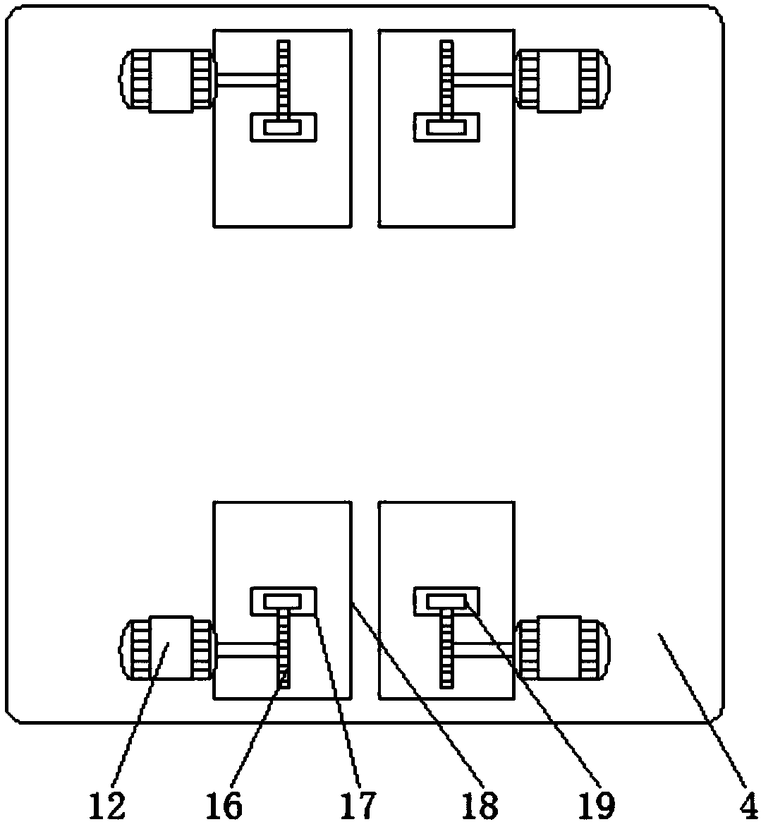
[0025] Embodiment three, refer to Figure 2-4 , the four motors 12 are all connected to the gear plate 16 through the rotating shaft. One side of the gear plate 16 is meshed with a gear bar 19. The top position of one side of the gear bar 19 is welded with a limit block 20, and the bottom of the gear bar 19 is welded with a The top of the support plate 18 and the bottom plate 4 are located on the outside of each gear bar 19, and a limit hole 17 is opened. The motor 12 drives the gear plate 16 to rotate to drive the gear bar 19 to move up and down, thereby driving the support plate 18 to move up and down to move the furniture. When reaching the top of the handling device, move the support plate 18 down to contact with the contact surface and hold up the universal wheel 5, which can enhance the stability of the handling device, thereby preventing the furniture from appearing in the process of moving to the handling device. The phenomenon of movement is conducive to the progress ...


PUM


Abstract

A conveying device for furniture production comprises a conveying device main body, a connecting rod is welded at the horizontal center line position of the top of the conveying device main body, a spacer rod is welded inside the connecting rod, a pusher is welded at one end of the top of the conveying device main body, and a plurality of rectangular through holes are equally spaced at the top ofthe conveying device main body. In this invention, an elastic rope for connecting two sides is arranged between the pusher and the rotating plate, the conveying device can two pieces of furniture, Moreover, when the furniture is placed on the top of the conveying device body, an elastic rope is used to connect the pusher hand and the rotating plate so as to realize the omni-directional enclosure of the furniture, thereby enhancing the stability of the furniture placed on the conveying device body, and preventing the furniture from slipping due to the bumping in the moving process of the conveying device.

Description

technical field [0001] The invention relates to the technical field of furniture production, in particular to a transport device for furniture production. Background technique [0002] Furniture refers to the categories of utensils and facilities necessary for human beings to maintain normal life, engage in production practice and carry out social activities. Compared with large furniture, in recent years, in order to adapt to changes in market demand and people's life philosophy, smaller furniture Small-sized furniture is becoming more and more popular in the market. Many well-known furniture brands that have been focusing on selling standard-sized furniture have also begun to extend their business tentacles to small-sized furniture, whether it is larger or smaller. During the process, it is inconvenient to move, thereby inconvenient to process, so a furniture handling device for furniture production is needed. [0003] However, there are still some deficiencies in the use...

Claims


Application Information

Patent Timeline
Patent Type & Authority Applications(China)
IPC IPC(8): B62B3/04B62B5/04
CPCB62B3/04B62B5/049B62B2202/30
Inventor 邓文
Owner 邓文
Learn More