
Pipe take-up device and method

A wire take-up device and pipe technology, which is used in packaging, transportation and packaging, and transportation of filamentous materials, etc., can solve the problems of gas accumulation in the pipe and instability of the upper plate, so as to improve production efficiency, avoid pipe filling, and save manpower. Effect

Pending Publication Date: 2018-12-11
SHENZHEN WOER HEAT SHRINKABLE MATERIAL +1
View PDF12 Cites 1 Cited by
  • Summary
  • Abstract
  • Description
  • Claims
  • Application Information

AI Technical Summary

Problems solved by technology

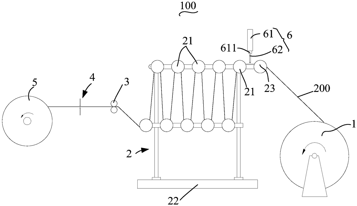
In the process of automatic rolling and packaging, because the device for calculating the number of meters will compress the pipe, the pipe will accumulate gas from this place. After running for a period of time, the subsequent flat pipe will become a round pipe due to the increase of internal gas, thus lead to unstable

Method used


Image

  • Pipe take-up device and method
  • Pipe take-up device and method
  • Pipe take-up device and method

Examples


Embodiment Construction

[0035] The following will clearly and completely describe the technical solutions in the embodiments of the present invention with reference to the accompanying drawings in the embodiments of the present invention. Obviously, the described embodiments are only part of the embodiments of the present invention, not all of them. Based on the embodiments of the present invention, all other embodiments obtained by persons of ordinary skill in the art without creative efforts fall within the protection scope of the present invention.

[0036] It should be noted that all directional indications (such as up, down, left, right, front, back...) in the embodiments of the present invention are only used to explain the relationship between the components in a certain posture (as shown in the accompanying drawings). Relative positional relationship, movement conditions, etc., if the specific posture changes, the directional indication also changes accordingly.

[0037] In the present invent...


PUM


Abstract

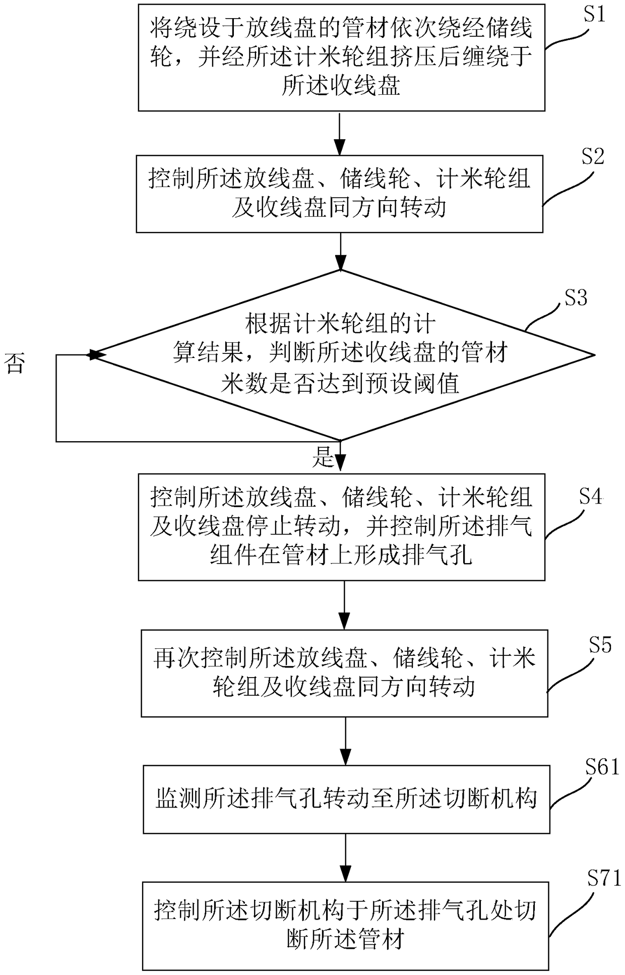
The invention discloses a pipe take-up device and method. The pipe take-up device comprises a pay-off spool, a wire storage wheel set, a meter counting wheel set and a take-up spool. The pay-off spool, the wire storage wheel set, the meter counting wheel set and the take-up spool are sequentially placed in an assembly line manner and rotate in the same direction. The wire storage wheel set comprises at least one wire storage wheel. A cut-off mechanism is arranged between the meter counting wheel set and the take-up spool. An exhaust assembly is arranged between the pay-off spool and the wire storage wheel set or is arranged in the wire storage wheel set. Pipes are wound on the pay-off spool. The pipes wound out from the pay-off spool are wound around the wire storage wheels and are wound on the take-up spool after being squeezed by the meter counting wheel set. The exhaust assembly and the cut-off mechanism are located above or below the pipes. The exhaust assembly is used for formingexhaust holes in the pipes. The cut-off mechanism is used for cutting off the pipes when the take-up spool reaches a preset meter number. By means of the technical scheme, gas in the pipes can be effectively removed, and the curling and packaging stability of the pipes can be improved.

Description

technical field [0001] The invention relates to the technical field of pipe packaging, in particular to a pipe take-up device and a pipe take-up method using the device. Background technique [0002] Tubing, such as flexible flat tubing, heat shrink tubing, needs to be flattened for packaging and shipping. Usually, the process of rolling and packaging rubber-plastic or heat-shrinkable hoses is called upper coiling. After winding and rolling 10,000-meter-long continuous rubber-plastic or heat-shrinkable hoses, they are cut into 100-meter-level smallest packaging rolls, and then rolled. Stretch film is wrapped around the wrap to avoid damage to the surface of the rolled object due to friction and collision during transportation. In the process of automatic rolling and packaging, because the device for calculating the number of meters will compress the pipe, the pipe will accumulate gas from this place. After running for a period of time, the subsequent flat pipe will become a...

Claims


Application Information

Patent Timeline
Patent Type & Authority Applications(China)
IPC IPC(8): B65H51/22B65H61/00B65B63/04
CPCB65B63/04B65H51/22B65H61/00B65H2701/33
Inventor 熊鑫张维波
Owner SHENZHEN WOER HEAT SHRINKABLE MATERIAL
Learn More