Method and device for evacuating turbine condenser

A technology of condenser and auxiliary condenser, applied in steam/steam condensers, steam engine installations, machines/engines, etc., can solve problems such as loss of propulsion steam

Inactive Publication Date: 2003-08-06
SIEMENS AG
View PDF0 Cites 1 Cited by
  • Summary
  • Abstract
  • Description
  • Claims
  • Application Information

AI Technical Summary

Problems solved by technology

[0004] The main disadvantage of this arrangement is that the propulsion steam normally discharged by the water / steam circuit of the steam turbine is lost, so that the water inlet circuit of the turbine condenser has to be filled by a corresponding amount of water inlet
This loss of influent water increases with the number of start-up processes and includes the additional cost of required influent water treatment

Method used


Image

  • Method and device for evacuating turbine condenser
  • Method and device for evacuating turbine condenser

Examples


Embodiment Construction

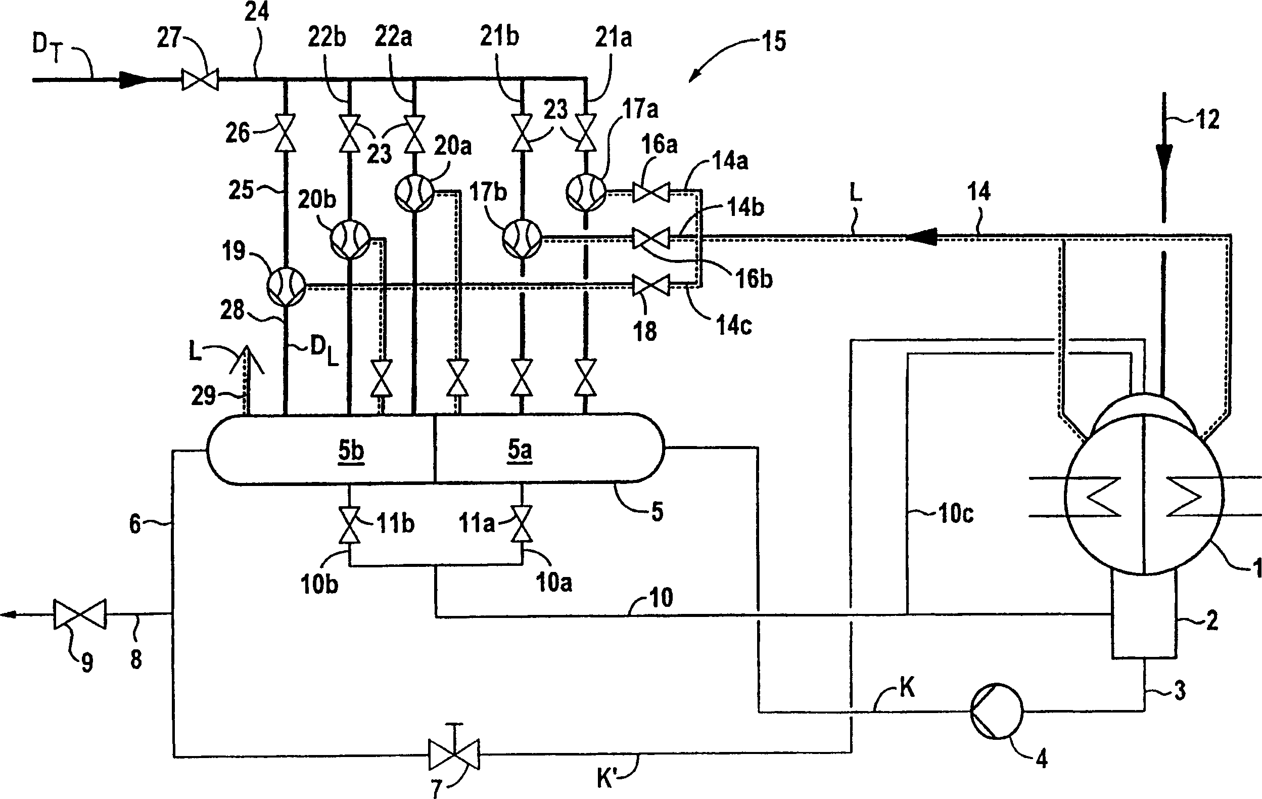
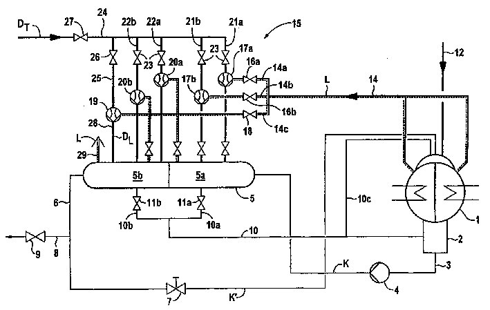
[0013] The main condenser or turbo condenser 1 of a steam turbine plant (not shown) is connected at its outlet end by means of its condensate collector 2 to a condensate main 3 which is connected via a condensate pump 4 to the inlet end of an auxiliary condenser 5 . At its outlet end, the secondary condenser 5 is connected to the main condenser 1 via a condensate header 6 . In the condensate main 6, there is a flow control valve 7 for regulating the amount of cooling condensate required for start-up operation. For example, the condensate is directed to the steam generator heating surface and a circulation main 8 is connected to the condensate main 6 with a control valve 9 which is closed during start-up operation.

[0014] The condensed water K collected in the auxiliary condenser 5 is guided to the condensed water collector 2 of the main condenser 1 through the condensed water main 10 . For this purpose, the condensate main 10 is connected to the first pressure stage 5a or ...


PUM


Abstract

In order to evacuate a turbine condenser, air (L) contained in the turbine condenser (1) is suctioned using propellant steam from a starting jet pump (19). According to the invention, the propellant steam (D) and the air (L) are guided into an auxiliary condenser (5) which is arranged downstream from said turbine condenser (1).

Description

technical field [0001] The invention relates to a method of venting a turbo condenser, in particular during start-up operation. It also relates to a device for implementing the method Background technique [0002] During operation of a steam turbine plant, usually steam formed in a steam generator and expanded in the steam turbine to produce work is condensed in a condenser connected downstream of the steam turbine. The condensed water that occurs in the turbine condenser is returned to the water / steam circuit of the steam turbine. In order to extract the air contained in the turbo condenser or the main condenser during operation of the turbo plant, so-called operational jet pumps are usually used. These are connected to the propellant steam main and to a secondary condenser which is connected downstream of the main condenser. The air header connected to the main condenser is connected to the suction side of a working jet pump, which operates on the jet pump principle. ...

Claims


Application Information

Patent Timeline
Patent Type & Authority Applications(China)
IPC IPC(8): F01K9/02F28B1/02F28B9/10
CPCF01K9/02
Inventor 托马斯·科尼格沃尔夫冈·莱曼
Owner SIEMENS AG
Why Eureka
Try Eureka