A tent that uses solar energy to generate electricity by itself

A technology of self-generation and solar energy, applied in tents/canopies, current collectors, electric vehicles, etc., can solve the problems of not having the power supply demand of solar tents, tents not having self-power generation function, and inconvenient assembly and construction, etc., to achieve assembly and construction Convenience, easy promotion and application, and simple structure

Active Publication Date: 2020-05-19
唐山尚达科技有限公司
View PDF7 Cites 0 Cited by
  • Summary
  • Abstract
  • Description
  • Claims
  • Application Information

AI Technical Summary

Problems solved by technology

Only by knowing the names and usage methods of each component and being familiar with the structure of the tent can we quickly and conveniently set up the tent. The existing tents do not have the function of self-power generation, do not have the need to use solar energy to maintain the power supply in the tent, and are not convenient to assemble and build. Also does not have the adjustment function, the present invention provides a tent that utilizes solar energy to generate electricity

Method used


Image

  • A tent that uses solar energy to generate electricity by itself
  • A tent that uses solar energy to generate electricity by itself
  • A tent that uses solar energy to generate electricity by itself

Examples


Embodiment 1

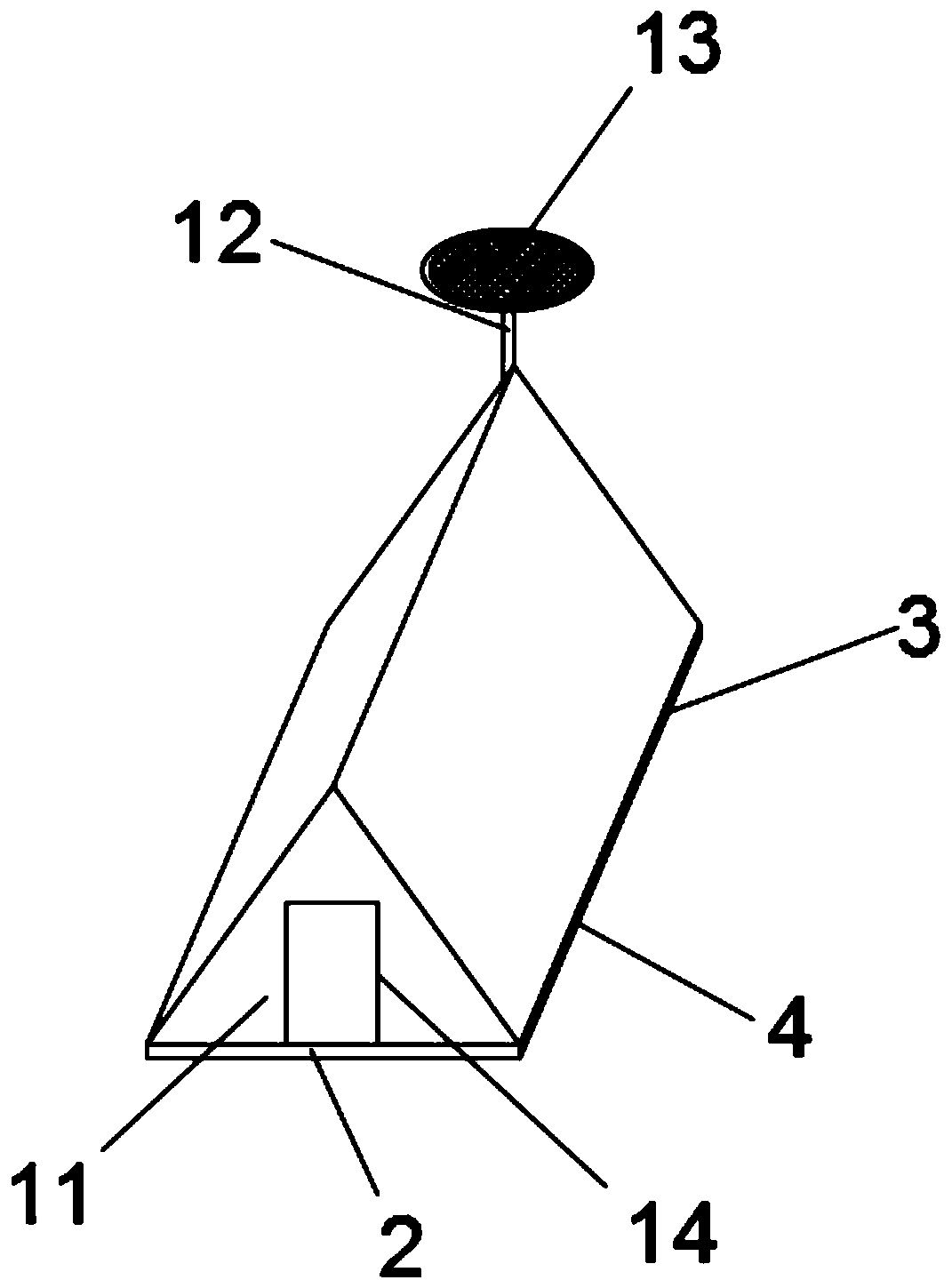
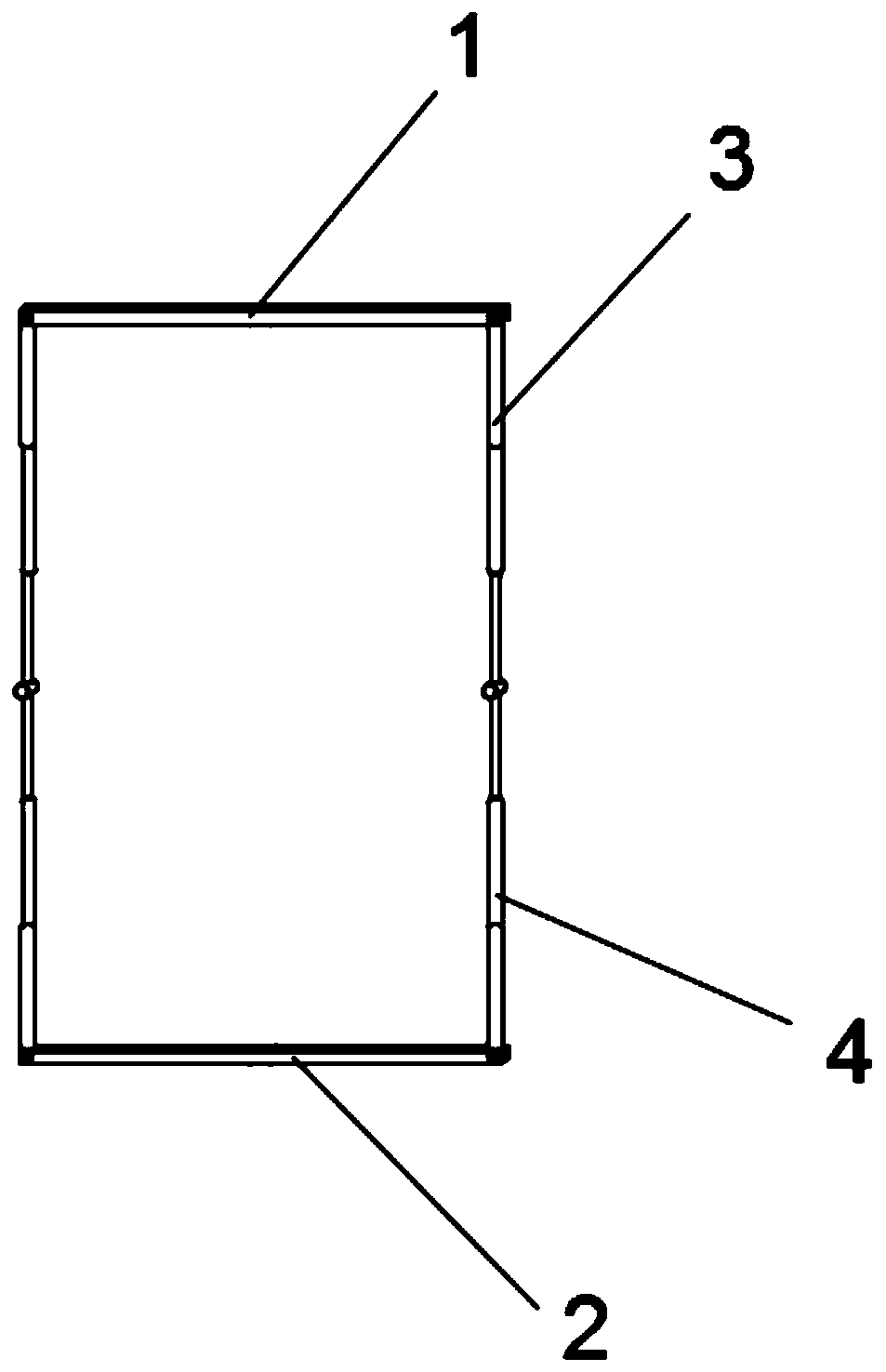
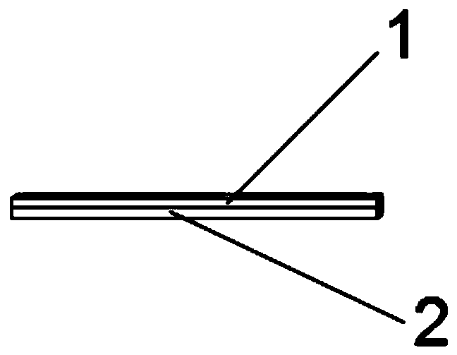
[0026] Embodiment 1: as Figure 1-12 As shown, a tent that utilizes solar energy to generate electricity by itself includes a first U-shaped chassis 1 and a second U-shaped chassis 2, and the two ends of the side walls of the first U-shaped chassis 1 are rotatably connected with first telescopic rods. 3. The two ends of the side wall of the second U-shaped bottom frame 2 are rotatably connected to the second telescopic rod 4, and the first telescopic rod 3 and the second telescopic rod 4 are movable hinged, and the first U-shaped bottom The tops of the frame 1 and the second U-shaped underframe 2 are all fixedly connected with a mounting frame 5, the bottom left end of the mounting frame 5 is rotatably connected with a first support frame 6, and the right side inner wall of the mounting frame 5 is rotatably connected with a The second support frame 7, the right end of the first support frame 6 is fixedly connected with a pin shaft 19, the right side of the pin shaft 19 is fixe...

Embodiment 2

[0027] Embodiment 2: as Figure 1-12 As shown, a tent that utilizes solar energy to generate electricity by itself includes a first U-shaped chassis 1 and a second U-shaped chassis 2, and the two ends of the side walls of the first U-shaped chassis 1 are rotatably connected with first telescopic rods. 3. The two ends of the side wall of the second U-shaped bottom frame 2 are rotatably connected to the second telescopic rod 4, and the first telescopic rod 3 and the second telescopic rod 4 are movable hinged, and the first U-shaped bottom The tops of the frame 1 and the second U-shaped underframe 2 are all fixedly connected with a mounting frame 5, the bottom left end of the mounting frame 5 is rotatably connected with a first support frame 6, and the right side inner wall of the mounting frame 5 is rotatably connected with a The second support frame 7, the right end of the first support frame 6 is fixedly connected with a pin shaft 19, the right side of the pin shaft 19 is fixe...


PUM


Abstract

The invention discloses a solar energy self-generating tent. The solar energy self-generating tent comprises two U-shaped bottom frames, both ends of the side wall of each U-shaped bottom frame are rotatingly connected with a first retractable rod and a second retractable rod respectively which are movably hinged; the tops of the two U-shaped bottom frames are fixedly connected with a mounting frame which is rotatingly connected with a first support frame and a second support frame; the side walls of the U-shaped bottom frames are fixedly connected with a plurality of positioning rings and winding mechanisms, steel wires are wound inside the winding mechanisms, and one end of every steel wire is fixedly connected with a hook; the outside of a framework is covered by a tent cloth. The solarenergy self-generating tent is convenient to assemble and build and can be retracted and folded for convenient storage and carrying; meanwhile, the solar energy self-generating tent has an adjustingfunction and meets inside power supply demands through solar energy, thereby being easy to popularize and apply.

Description

Technical field: [0001] The invention specifically relates to a tent that utilizes solar energy to generate electricity by itself. Background technique: [0002] A tent is a shed that is propped on the ground to shelter from wind, rain, sunlight and for temporary living. It is mostly made of canvas, and together with the supporting things, it can be removed and transferred at any time. The tent is carried in parts and assembled after arriving at the site, so various parts and tools are required. Only by knowing the names and usage methods of each component and being familiar with the structure of the tent can we quickly and conveniently set up the tent. The existing tents do not have the function of self-power generation, do not have the need to use solar energy to maintain the power supply in the tent, and are not convenient to assemble and build. Also does not have the adjustment function, the present invention provides a kind of tent that utilizes solar energy self-gene...

Claims


Application Information

Patent Timeline
Patent Type & Authority Patents(China)
IPC IPC(8): E04H15/02E04H15/46H02J7/35
CPCE04H15/02E04H15/46H02J7/35
Inventor 汪六一朱大伟
Owner 唐山尚达科技有限公司
Why Eureka
Try Eureka