A battery bearing device for an electric vehicle

A technology for bearing devices and electric vehicles, which is applied in the direction of electric vehicles, secondary batteries, battery pack components, etc., can solve the problems of large cooling equipment, impact on the performance of battery equipment, and fires, so as to improve the comprehensive utilization of resources , to achieve the effect of recycling, improving capacity and efficiency

Inactive Publication Date: 2018-12-11
安利平 +2
View PDF9 Cites 0 Cited by
  • Summary
  • Abstract
  • Description
  • Claims
  • Application Information

AI Technical Summary

Problems solved by technology

[0002] At present, the electric energy used by electric vehicle equipment is provided by batteries. In actual use, it is found that when the ambient temperature is too low during the operation of electric vehicle battery equipment, the charging and discharging performance of battery equipment will be greatly affected. However, when the ambient temperature is high and the operation of the battery equipment generates a large amount of heat, if the battery cannot be cooled in a timely and effective manner, the performance of the battery equipment will be seriously affected, and even cause a fire. This phenomenon seriously affects the operation performance and safety of electric vehicles. To solve this problem, the current cooling equipment used in electric vehicle batteries is often traditional cooling fans and other equipment. Although they can meet the needs of use, on the one hand, the cooling efficiency is poor. It cannot effectively meet the needs of the operation of electric vehicles. On the other hand, the cooling equipment is relatively large in size and needs to occupy a large space in the vehicle. At the same time, it also leads to a complicated layout of the equipment in the vehicle. While reducing the comprehensive use efficiency of the vehicle, it increases The difficulty and cost of daily maintenance of vehicles, so in view of this situation, it is urgent to develop a new cooling device to meet the needs of actual use

Method used


Image

  • A battery bearing device for an electric vehicle

Examples


Embodiment Construction

[0014] In order to make the technical means, creative features, goals and effects achieved by the present invention easy to understand, the present invention will be further described below in conjunction with specific embodiments.

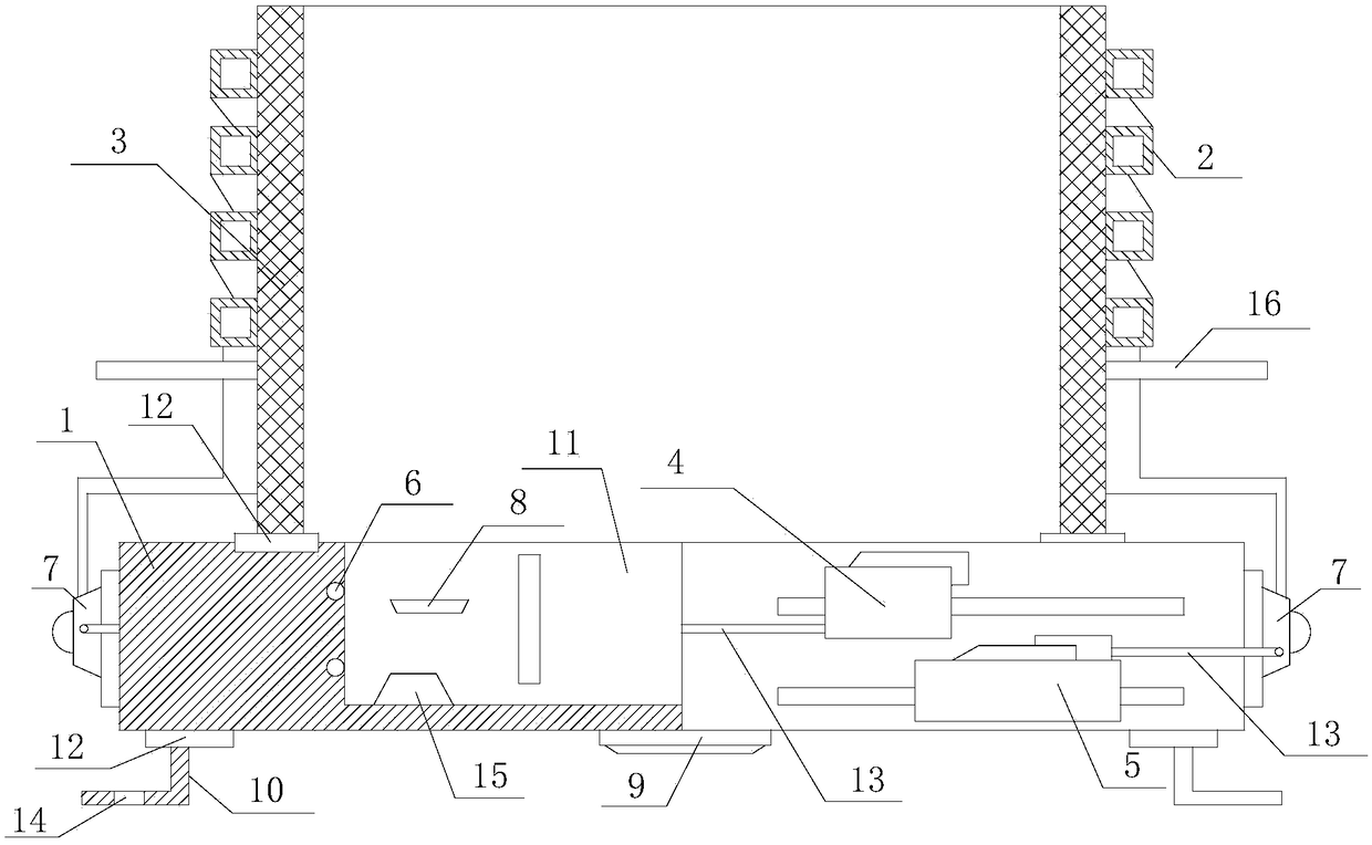
[0015] Such as figure 1 The electric vehicle battery carrying device includes a carrying base 1, a heat exchange tube 2, a heat exchange plate 3, a thermoelectric power generation device 4, a semiconductor refrigeration device 5, an electric heating wire 6, a ventilation fan 7, a temperature sensor 8 and The control circuit 9 is provided with at least two positioning mechanisms 10 on the lower end of the bearing base 1, and the upper end is provided with a positioning groove 11 with a cross-section in the shape of "凵", the positioning groove 11 is coaxially distributed with the bearing base 1, and the heat exchange plate 3 is positioned around The axes of the grooves 11 are evenly distributed, and the front end surface is parallel to the axes of t...


PUM


Abstract

The invention relates to a battery bearing device for an electric vehicle. The device includes a bearing base, heat exchange tubes, plates, thermoelectric generator, semiconductor refrigerator, electric heating wire, ventilating fan, Temperature sensor and control circuit, A low end face setting position mechanism of a bearing base An upper end face set position groove, A heat exchange plate is uniformly distributed around the axis of the positioning groove, A low end face is slidably connected with an upper end face of a load-bearing base through a guide rail, A heat exchange tube is embeddedin the rear end face of the heat exchange plate, the air inlet and the air outlet of the heat exchange tube are respectively communicated with the ventilation fan, the thermoelectric power generationdevice and the semiconductor refrigeration device are installed on the side surface of the bearing base, the electric heating wire is embedded on the inner surface of the sidewall of the positioninggroove, and the control circuit is installed on the lower end face of the bearing base. On the one hand, the invention can effectively satisfy the effective bearing positioning of the battery equipment for the electric vehicle; on the other hand, the invention can greatly improve the capacity and efficiency of regulating the temperature of the battery when the battery is running, and can effectively realize the recovery and utilization rate of the heat energy.

Description

technical field [0001] The invention relates to a cooling device, in particular to an electric vehicle battery carrying device. Background technique [0002] At present, the electric energy used by electric vehicle equipment is provided by batteries. In actual use, it is found that when the ambient temperature is too low during the operation of electric vehicle battery equipment, the charging and discharging performance of battery equipment will be greatly affected. However, when the ambient temperature is high and the operation of the battery equipment generates a large amount of heat, if the battery cannot be cooled in a timely and effective manner, the performance of the battery equipment will be seriously affected, and even cause a fire. This phenomenon seriously affects the operation performance and safety of electric vehicles. To solve this problem, the current cooling equipment used in electric vehicle batteries is often traditional cooling fans and other equipment. A...

Claims


Application Information

Patent Timeline
Patent Type & Authority Applications(China)
IPC IPC(8): H01M2/10H01M10/613H01M10/615H01M10/6552H01M10/6554H01M10/6563H01M10/6571H01M10/6572B60L11/18
CPCH01M10/613H01M10/615H01M10/6552H01M10/6554H01M10/6563H01M10/6571H01M10/6572H01M50/20Y02E60/10Y02T10/70
Inventor 安利平曹翠梅曹丽
Owner 安利平
Why Eureka
Try Eureka